System and method for cooling high-carbon steel wire rod after rolling

A technology of cooling system and cooling method, applied in the direction of metal rolling, metal rolling, workpiece surface treatment equipment, etc., can solve the problems of uneven cooling of wire rod 2, large fluctuations in microstructure, high proportion of upper bainite, etc.

Active Publication Date: 2014-04-30
BAOSHAN IRON & STEEL CO LTD
View PDF4 Cites 1 Cited by
  • Summary
  • Abstract
  • Description
  • Claims
  • Application Information

AI Technical Summary

Problems solved by technology

However, due to the fact that the distribution of the wire rod on the roller table is different from the theoretical situation in actual production, please refer to the attached figure 1 As shown, the two sides of the wire rod 2 rolled by the laying machine 1 are not neat and uniform, and the cooling of each area of ​​the wire rod 2 is uneven, especially the outer part of the overlapping area H is over-cooled, resulting in the entire cooling after cooling The microstructure fluctuates greatly on the wire rod 2, and the proportion of upper bainite is high
Therefore, although this method can make the mechanical properties of the wire rod close to the salt bath treatment, the broken wire rate in the subsequent cold drawing process is much higher than that of the wire rod produced by the ordinary Stelmore process or the salt bath process.

Method used


Image

  • System and method for cooling high-carbon steel wire rod after rolling
  • System and method for cooling high-carbon steel wire rod after rolling
  • System and method for cooling high-carbon steel wire rod after rolling

Examples


Embodiment Construction

[0025] The technical solutions of the present invention are further described below with reference to the accompanying drawings and embodiments.

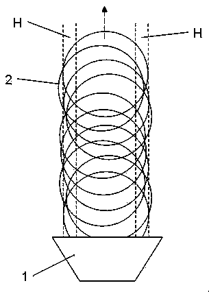
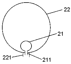
[0026] see figure 2 As shown, the post-rolling cooling system for the high carbon steel wire rod of the present invention includes a Stellmor control cooling device 10 arranged on the outlet side of the laying head 1, so as to cool the wire rod 1 entering into the area of ​​the Stellmor control cooling device 10. Cooling (its structure and cooling principle are basically the same as those of traditional Stellmor cooling, and will not be repeated here). The cooling system also includes an aerosol pre-cooling device 20, which is arranged on the roller table 3 between the laying head 1 and the first cooling fan 11 of the Stellmor control cooling device 10. The overlapping area H of the strip 2 is sprayed with aerosol for cooling, and a forced convection steam film is formed on the surface of the wire rod in the overlapping area H, so...


PUM


Abstract

The invention discloses a system for cooling a high-carbon steel wire rod after rolling. The device comprises a Stelmor controlled cooling device and a gas fog pre-heating device, wherein the gas fog pre-heating device is arranged on a roller path between a laying head and the Stelmor controlled cooling device. The invention further discloses a method for cooling a high-carbon steel wire rod after rolling. The method comprises the following steps of: controlling the temperature difference among different areas of a rod body to be below 100 DEG C by using the high thermal conductivity of convection vapor during gas fog pre-cooling; and entering the Stelmor controlled cooling device at the temperature of 650-750 DEG C for performing Stelmor cooling. Compared with a wire rod subjected to salt treatment, the finally obtained wire rod in the invention has the advantages that: the mechanical performance and microscopic structure are very close, the tensile strength of cold drawing can be met, and environmental pollution is greatly lowered.

Description

technical field [0001] The invention relates to wire cooling technology, and more particularly, to a post-rolling cooling system and method for high-carbon steel wire rods. Background technique [0002] At present, there are two existing post-rolling cooling processes for high carbon steel wire rods, one is the Steyrmore controlled cooling method, and the other is the salt bath treatment process. The former is the most popular and widely used in the world. By adjusting the air volume of the cooling fan and adjusting the air volume distribution in the direction perpendicular to the running direction of the wire rod, it assists the speed difference between the wire rod dropping device and the different sets of roller tables. To control the microstructure and properties of the wire rod, although it has little impact on the environment, it can only meet the general requirements for the production of high-carbon steel wire rods, but cannot produce high-performance wire rods with ...

Claims


Application Information

Patent Timeline
Patent Type & Authority Patents(China)
IPC IPC(8): B21B45/02B21B37/74
Inventor 胡东辉
Owner BAOSHAN IRON & STEEL CO LTD
Why Eureka
Try Eureka