Scroll compressor

A technology of scroll compressors and compression chambers, which is applied in the direction of rotary piston machines, rotary piston pumps, mechanical equipment, etc., which can solve the problems of decreased suction heating performance, increased gas specific volume, and decreased energy efficiency, etc., to achieve suppression Effects of heating, high-efficiency scroll compressor, and prevention of sealing loss

Inactive Publication Date: 2012-05-16
HITACHI APPLIANCES INC
View PDF6 Cites 24 Cited by
  • Summary
  • Abstract
  • Description
  • Claims
  • Application Information

AI Technical Summary

Problems solved by technology

Therefore, the gas (working fluid such as refrigerant gas) flowing into the compressor from the suction pipe is heated, and the specific volume of the heated gas increases, so the quality of the working fluid taken into the compression chamber decreases.
Therefore, since the exi

Method used


Image

  • Scroll compressor
  • Scroll compressor
  • Scroll compressor

Examples


Embodiment 1

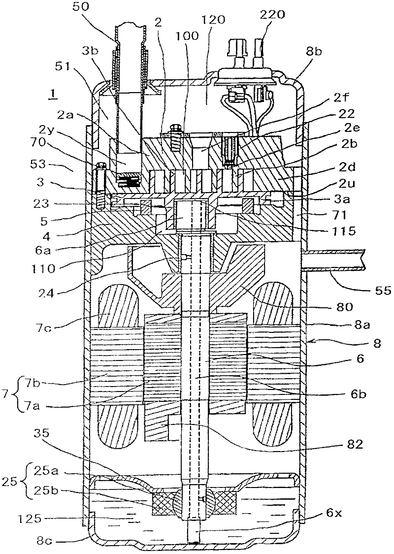
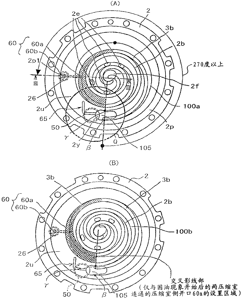
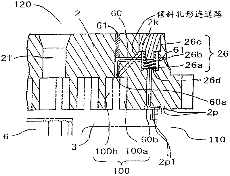
[0064] based on Figure 1 to Figure 6 Example 1 of the present invention will be described. figure 1 is a longitudinal sectional view showing the scroll compressor of this embodiment, figure 2 is true figure 1 The bottom view of the fixed scroll shown is viewed from below, (A) is a diagram including the orbiting scroll wrap (scro-lulap) when the oil trapping phenomenon starts in the compression chamber on the rotating outer line side, and (B) is a diagram At the same time, the figure of the orbiting scroll scroll at the beginning of the oil trapping phenomenon in the compression chamber on the rotating inner line side is included, image 3 yes figure 2 The III-III sectional view of the fixed scroll shown is a diagram for explaining the structure near the back pressure valve. Figure 4 is true figure 1 The orbiting scroll shown is a top view from above, Figure 5 yes Figure 4 The V-V line sectional view of the orbiting scroll shown, Figure 6 will be figure 2The pa...

Embodiment 2

[0103] Next, use Figure 7 Embodiment 2 of the scroll compressor of the present invention will be described. In this embodiment, an externally driven throttle valve is provided in the suction area communicating passage, and the amount of oil supplied from the back pressure chamber to the suction area is adjusted by controlling the externally driven throttle valve. The other structures are basically the same as those of the above-mentioned embodiment 1, so repeated explanations are omitted.

[0104]This Example 2 is further described in detail. The suction area communication path 65' in this embodiment is set to communicate with the back pressure chamber 110 of the scroll compressor 1 and the suction hole 2y of the suction area 105 in the flow path of the working fluid from the suction pipe 50 to the compression chamber 100, and An externally driven throttle valve (flow rate control valve) 65c whose opening can be controlled by a control device 65g provided outside the scroll...

Embodiment 3

[0110] use Figure 8 ~ Figure 10 Embodiment 3 of the scroll compressor of the present invention will be described. Figure 8 is a top view of the orbiting scroll in this embodiment, Figure 9 yes Figure 8 A longitudinal sectional view of the orbiting scroll, is Figure 8 Sectional view of line IX-IX, Figure 10 It is an enlarged view of the vicinity of the suction pipe on the fixed end plate surface of the fixed scroll in this embodiment, which is equivalent to figure 2 A diagram of the Q section. In this embodiment 3, the parts with the same symbols as those in the above-mentioned embodiment 1 represent the same or corresponding parts.

[0111] In this embodiment 3, instead of the rotating end plate oil supply hole 65a in the above-mentioned embodiment 1, a rotating end plate is provided at a position of the rotating end plate 3a in the orbiting scroll 3 facing the fixed end plate surface 2u. Oil supply recessed portion (recessed portion) 65A. In addition, an arc-sha...


PUM

PropertyMeasurementUnit
Diameteraaaaaaaaaa

Abstract

The invention provides a scroll compressor, which prevents the sealing performance at the utmost external engaged part of a fixed scroll and a revolving scroll from decreasing and inhibits the heating of a working fluid within a suction zone so as to realize the high energy efficiency. The scroll compressor, comprises a fixed scroll, a revolving scroll rotating through being engaged with the fixed scroll so as to form a compression chamber between the fixed scroll and the revolving scroll, and an oil supply way which supplies oil to a back pressure chamber used for exerting an extrusion force on the fixed scroll from the revolving scroll, and to the discharge side of the back pressure chamber to the compressor. The compressor also comprises a compression chamber communicating passage and a suction zone communicating passage. The compression chamber communicating passage comprises a back pressure valve, which is communicated only with the compression chamber after the oil blocking phenomenon and is opened or closed through the pressure difference from start to finish. Therefore, oil in the back pressure chamber flows towards the compression chamber, so that the pressure of the back pressure chamber is controlled. The suction zone communicating passage only communicates the back pressure chamber with the suction zone of the compression chamber so as to supply oil to the suction zone.

Description

technical field [0001] The present invention relates to a scroll compressor with a fixed scroll and an orbiting scroll engaged with it, especially suitable for CO 2 Scroll compressors for refrigeration cycles that compress refrigerants such as , HFC, etc. Background technique [0002] As a conventional scroll compressor, there is a compressor as described in Patent Document 1, that is, the oil in the discharge space is introduced into the back surface of the orbiting scroll to form a back surface whose pressure is intermediate between the discharge pressure and the suction pressure. The pressure chamber uses the pressure of the back pressure chamber (hereinafter referred to as "back pressure") to bias the orbiting scroll toward the fixed scroll. [0003] This type of scroll compressor discharges the oil introduced into the back pressure chamber from the discharge space to the compression chamber through a communication path provided with a back pressure valve for controllin...

Claims


Application Information

Patent Timeline
IPC IPC(8): F04C18/02
CPCF04C18/0215F04C18/0269F04C29/028F04C29/124F04C2210/26F04C2240/40Y10S415/00Y10S417/902
Inventor 坪野勇向井有吾石山明彦津久井和则佐藤英治
Owner HITACHI APPLIANCES INC
Why Eureka
Try Eureka