Electric valve

An electric valve and valve needle technology, applied in the field of control valves, can solve the problems of short service life of electric valves, eccentric wear of the valve port, misalignment between the valve needle and the valve port, etc., so as to improve the operation reliability, avoid eccentric wear, The effect of improving coaxiality

Inactive Publication Date: 2012-05-16
ZHEJIANG SANHUA INTELLIGENT CONTROLS CO LTD
View PDF13 Cites 62 Cited by
  • Summary
  • Abstract
  • Description
  • Claims
  • Application Information

AI Technical Summary

Problems solved by technology

[0004] The patent document (JP-A-2010-25932) discloses an electric valve. The nut of the nut assembly is fixed in the guide sleeve, the guide sleeve is fixed on the valve seat, and the valve needle needs to be fixed in the valve port of the valve seat. Therefore, the coaxiality between the valve seat and the nut is highly required. The above-mentioned electric valve needs to be indirectly controlled through multiple assembly processes to ensure the coaxiality between the valve core seat and the nut, and the coaxiality between the valve seat and the nut is affected by the nut, guide Affected by the processing accuracy of sleeve, valve seat, valve needle and other parts, the coaxiality is not easy to guarantee. If the valve core seat and the nut are not in the same axis, it is easy to appear that the valve needle and the valve port are not in the same axis, which will cause the valve The port seal is not tight or the valve port is eccentrically worn, which makes the reliability of the action of the electric valve lower, and the service life of the electric valve is also shorter.
[0005] In addition, it has become a development trend in this field to replace metal materials with plastic materials. In the above-mentioned electric valve, if the nut is made of plastic, it is not easy to ensure the connection strength and reliability of the connection between the nut and the guide sleeve only through interference fit. Low, so that the nut can not be made of plastic, but still have to use expensive metal material, so that the processing cost of the electric valve is relatively high

Method used


Image

  • Electric valve
  • Electric valve
  • Electric valve

Examples


Embodiment Construction

[0027] In order to enable those skilled in the art to better understand the technical solutions of the present invention, the present invention will be further described in detail below in conjunction with the accompanying drawings and specific embodiments.

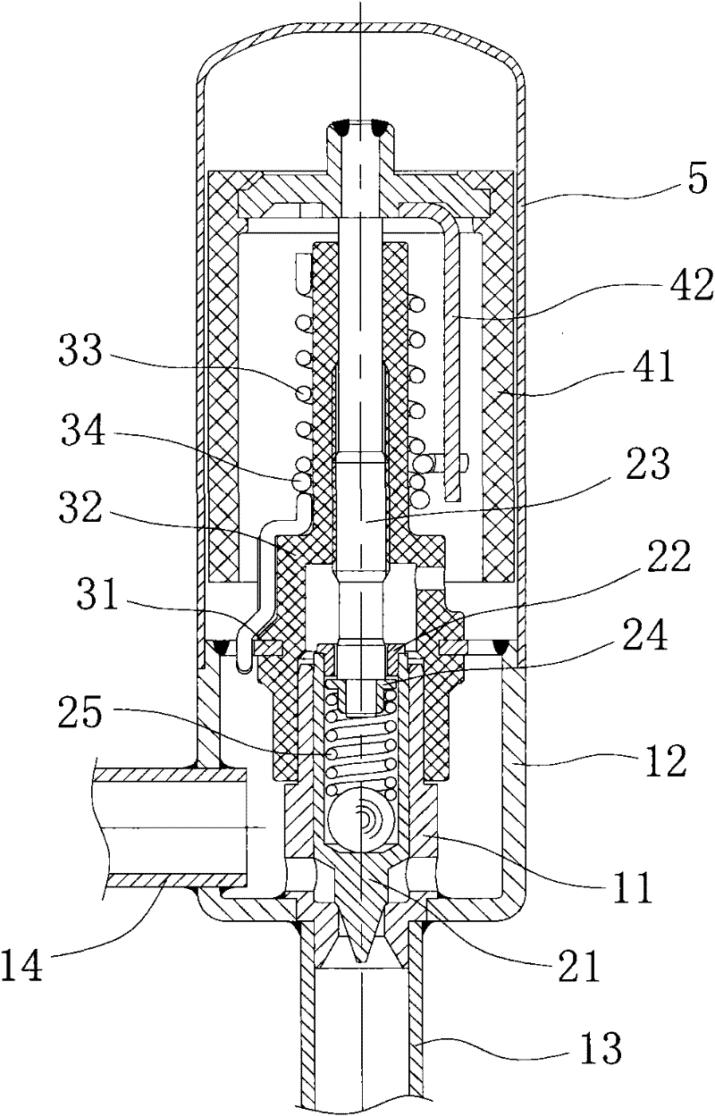
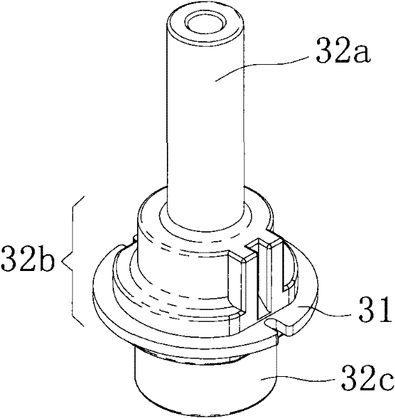
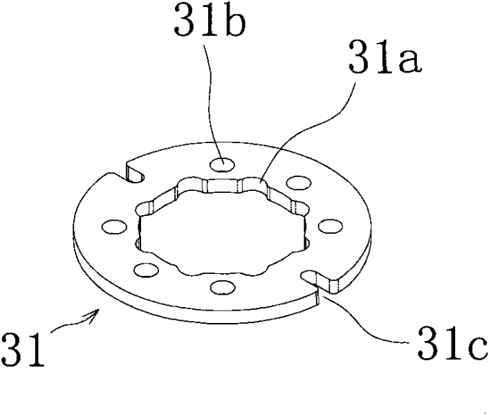
[0028] Please see Figure 1-Figure 4 , figure 1 It is a schematic cross-sectional structure diagram of a specific embodiment of the electric valve provided by the present invention; figure 2 for figure 1 Schematic diagram of the structure of the middle nut; image 3 for figure 2 Schematic diagram of the structure of the ring-shaped metal connecting piece; Figure 4 for figure 1 Schematic diagram of the structure when the electric valve is not installed in the shell.

[0029] Such as figure 1 As shown, the electric valve provided by the present invention includes a valve seat assembly, a nut assembly, a valve needle screw assembly and a rotor assembly.

[0030] Wherein, the valve seat assembly includes a valve co...


PUM


Abstract

The invention relates to the technical field of control valves, in particular to an electric valve for regulating fluid flow. The electric valve comprises a valve seat component, a nut component and a valve needle lead screw component, wherein the valve seat component comprises a valve seat and a valve core seat; the nut component comprises a nut for mounting the valve needle lead screw component; and the lower end of the nut is sleeved with the upper end of the valve core seat. By the electric valve, the lower end of the nut which is used for mounting the valve needle lead screw component is connected with the upper end of the valve core seat in a sleeved mode, so that the coaxiality of the nut and a valve port of the valve core seat is extremely easy to guarantee, the coaxiality of a valve needle and the valve core seat is higher, and the problem that the valve port is loosely sealed or is subjected to eccentric wear can be solved. Meanwhile, because the coaxiality of the valve needle and the valve port is improved, the friction force can be obviously reduced when a rotor of a rotor component rotates, and the action reliability of the electric valve can be improved.

Description

technical field [0001] The invention relates to the technical field of control valves, in particular to an electric valve for regulating fluid flow. Background technique [0002] In air conditioners, refrigerators, heat pump water heaters and various refrigeration and heating equipment, electric valves are usually used to regulate the flow of fluid. [0003] The electric valve usually includes a valve seat assembly, a nut assembly, a valve needle screw assembly, and a rotor assembly. The valve seat assembly usually includes a valve core seat, a valve seat and a connecting pipe. The tube is usually welded together to form the valve seat assembly, and the valve needle of the valve needle screw assembly is installed in the nut of the nut assembly. [0004] The patent document (JP-A-2010-25932) discloses an electric valve. The nut of the nut assembly is fixed in the guide sleeve, the guide sleeve is fixed on the valve seat, and the valve needle needs to be fixed in the valve po...

Claims


Application Information

Patent Timeline
Patent Type & Authority Applications(China)
IPC IPC(8): F16K31/04F16K31/50F16K1/42
CPCF16K31/047F16K1/34F16K25/02F16K31/04
Inventor 魏先让
Owner ZHEJIANG SANHUA INTELLIGENT CONTROLS CO LTD
Why Eureka
Try Eureka