Package structure of concentrated photovoltaic cell

A solar cell and packaging structure technology, applied in photovoltaic power generation, circuits, electrical components, etc., can solve problems such as dark current rise, circuit board detachment, and impact on the service life of solar chips, and achieve the effect of avoiding service life and good heat dissipation.

Inactive Publication Date: 2012-05-16
MILLENNIUM COMM
View PDF3 Cites 8 Cited by
  • Summary
  • Abstract
  • Description
  • Claims
  • Application Information

AI Technical Summary

Problems solved by technology

[0002] Concentrating solar cells mainly use lenses to gather sunlight in a small area to improve power generation efficiency. When using concentrating solar cells for electrical energy conversion, due to the limitation of the spectral absorption capacity of the material itself, it is impossible to 100% light Can be converted into electric energy output, so the excess energy entering the solar cell is easy to form heat energy and accumulate in the battery, causing the temperature of the component to rise, resulting in a large increase in the dark current inside the battery and reducing the conversion efficiency of the battery
[0003] In the solar cell packaging structure, generally, the solar chip is directly attached to the circuit board, and the solar chip and the circuit board are electrically connected by wire bonding, and then epoxy resin is directly poured to isolate the solar chip from the circuit board. Contact with the external environment; however, there is a considerable difference between the thermal expansion coefficients of epoxy resin, solar chips and circuit boards, so after a long period of use, epoxy resin is easily corroded by moisture and separated from the circuit board, resulting in the inability to completely cover the solar chips , so that the service life of the solar chip is affected; on the other hand, due to the difference in the thermal expansion coefficient of the solar chip and the circuit board, the heat dissipation efficiency of the solar chip is reduced

Method used


Image

  • Package structure of concentrated photovoltaic cell
  • Package structure of concentrated photovoltaic cell
  • Package structure of concentrated photovoltaic cell

Examples


Embodiment Construction

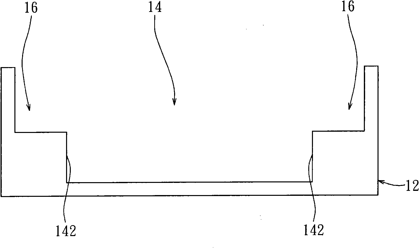
[0014] Figure 1A to Figure 1D Shown is a schematic cross-sectional view of a manufacturing method of a concentrating solar cell packaging structure according to an embodiment of the present invention; Figure 1A As shown, a ceramic base 12 is provided first, a groove 14 is formed on its upper surface, and two opposite inner sidewalls 142 of the groove 14 form a stepped structure 16 respectively. In one embodiment, the groove 14 and the stepped structure Structure 16 is integrally formed.

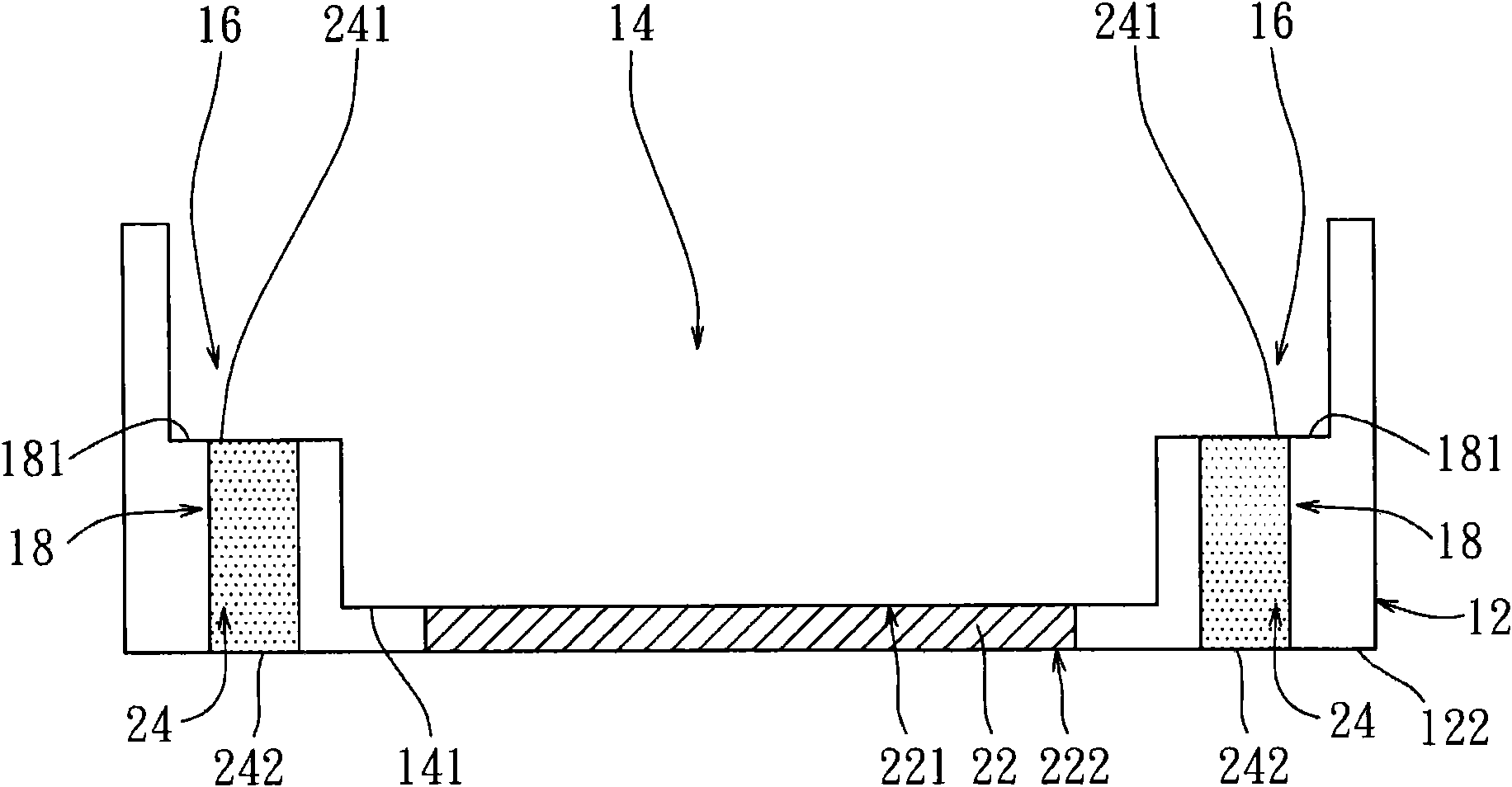
[0015] Next, if Figure 1B As shown, a first electrode line 22 and a second electrode line 24 are formed on the ceramic base 12, so that the first electrode line 22 and the second electrode line 24 penetrate the ceramic base 12, wherein the first electrode line 22 is vertically penetrated In the middle area of ​​the ceramic base 12, the top 221 and the bottom 222 of the first electrode line 22 are respectively exposed on the bottom surface 141 of the groove 14 and the lower surface 122 of ...


PUM


Abstract

A package structure of a concentrated photovoltaic cell includes a ceramic base plate whereon a cavity is formed, the cavity having two opposite internal walls respectively having staircase structures, each having an upper step and a lower step; a photovoltaic chip disposed on a bottom surface of the cavity; a first electrode circuit path penetrating the ceramic base plate and with a top end electrically connected to the photovoltaic chip; a second electrode circuit path penetrating the lower steps on the two sides of the ceramic base plate and connecting with the photovoltaic cell through metal wires; and a transparent cover disposed on the upper steps for covering the cavity and the photovoltaic chip. A fabrication method for the aforementioned package structure is also provided. The aforementioned package structure has the advantages of being more efficient in heat dissipation and effective in protecting the photovoltaic chip.

Description

technical field [0001] The present invention relates to a manufacturing method of a concentrating solar cell packaging structure and its packaging structure, in particular to a concentrating solar cell packaging structure that uses a ceramic base with a stepped structure to cover a solar chip to improve heat dissipation efficiency. Manufacturing method and packaging structure thereof. Background technique [0002] Concentrating solar cells mainly use lenses to gather sunlight in a small area to improve power generation efficiency. When using concentrating solar cells for electrical energy conversion, due to the limitation of the spectral absorption capacity of the material itself, it is impossible to 100% light It can be converted into electric energy output, so the excess energy entering the solar cell is easy to form heat energy and accumulate in the battery, causing the temperature of the component to rise, resulting in a large increase in the dark current inside the batt...

Claims


Application Information

Patent Timeline
Patent Type & Authority Applications(China)
IPC IPC(8): H01L31/18H01L31/048H01L31/052H01L31/05
CPCH01L31/052H01L31/02013Y02E10/52H01L31/048H01L2224/48091H01L2924/00014
Inventor 张诒安赖利弘
Owner MILLENNIUM COMM
Why Eureka
Try Eureka