Power factor correction (PFC) circuit and control method

A power factor correction and circuit technology, applied in the power supply field, can solve the problems of high power density and difficult to apply in high-power applications, and achieve the effect of increasing rate density, overcoming serious common-mode noise interference, and reducing high-frequency loss.

Inactive Publication Date: 2012-05-16
ZTE CORP
View PDF5 Cites 9 Cited by
  • Summary
  • Abstract
  • Description
  • Claims
  • Application Information

AI Technical Summary

Problems solved by technology

The totem-type bridgeless PFC circuit uses fewer devices and has a highe

Method used


Image

  • Power factor correction (PFC) circuit and control method
  • Power factor correction (PFC) circuit and control method
  • Power factor correction (PFC) circuit and control method

Examples


Embodiment Construction

[0039] In order to make the object, technical solution and advantages of the present invention clearer, the present invention will be further described in detail below in conjunction with the accompanying drawings.

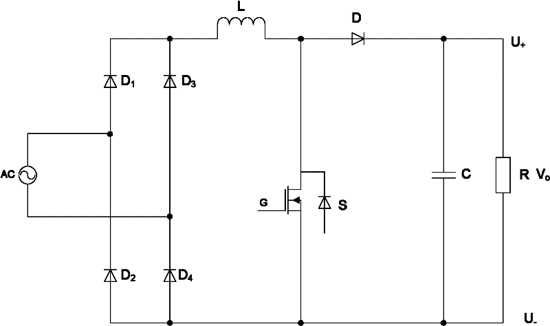
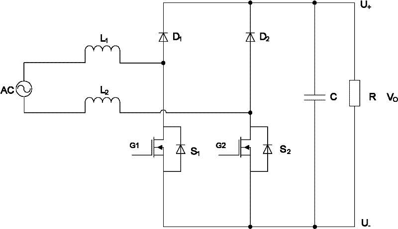
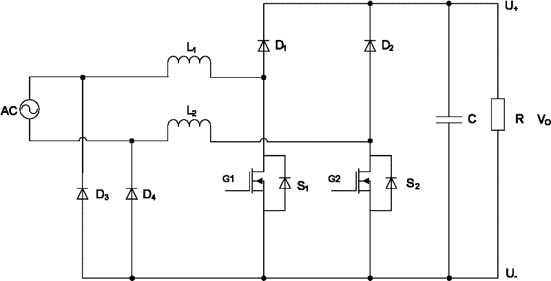
[0040] Aiming at the problems existing in the existing bridgeless PFC circuit, the present invention proposes a high-efficiency, high-power-density power factor correction (PFC) circuit and control method, using the low impedance path of the controllable switching device S1 or S2 to provide continuous The conduction of the main power current loop reduces or eliminates the high-frequency reverse current caused by the slow recovery diode PN junction capacitance characteristics, reduces the high-frequency loss of the circuit, and greatly reduces the on-state loss of the power loop, thereby further Improved efficiency of bridgeless PFC topology. At the same time, this circuit also overcomes the problem of serious EMI common-mode noise interference in the traditional b...


PUM


Abstract

The invention discloses a power factor correction (PFC) circuit and a control method. According to a power frequency cycle, a first controllable switching device (S1) or a second controllable switching device (S2) is controlled to be turned on or off; in a power frequency positive half-cycle, the first controllable switching device (S1) is turned off while the second controllable switching device (S2) is turned on; and in a power frequency negative half-cycle, the second controllable switching device (S2) is turned off while the first controllable switching device (S1) is turned on. A main power current loop which is continuously switched on is provided through a low-impedance path of the first controllable switching device (S1) or the second controllable switching device (S2). By replacing a slow recovery diode with the controllable switching devices, the influence of a junction capacitance effect is eliminated, a reverse current of each switching cycle is remarkably reduced, the high-frequency loss of a line is reduced, and the efficiency of the PFC circuit is improved. By the invention, an electromagnetic interference (EMI) effect can be improved, the quantity of components is decreased, and efficiency and power density are improved.

Description

technical field [0001] The invention relates to the technical field of power supplies, in particular to a power factor correction circuit and a control method. Background technique [0002] Bridge rectifier PFC (Power Factor Correction, power factor correction) circuit is widely used in power supply products, such as figure 1 As shown in , a schematic diagram of a typical single-phase PFC circuit is shown. In the bridge rectifier PFC circuit, three switching devices participate in the work in each switching cycle, and the on-state loss is relatively large. In order to reduce the on-state loss, a bridgeless PFC circuit can be used, such as figure 2 As shown, a schematic diagram of a conventional bridgeless PFC circuit is shown. The bridgeless PFC circuit saves the rectifier bridge, and only two switching devices participate in the work in each switching cycle, so the on-state loss is reduced, and it has outstanding advantages in improving efficiency. but figure 2 The b...

Claims


Application Information

Patent Timeline
IPC IPC(8): H02M1/42
CPCH02M1/4208Y02B70/126H02M1/4225H02M1/4233Y02B70/10Y02P80/10H02M1/0085
Inventor 金亮亮罗勇
Owner ZTE CORP
Why Eureka
Try Eureka