Method of manufacturing a composite structure with prefabricated reinforcement element

A technology for reinforcing components and composite structures, applied in the direction of final product manufacturing, sustainable manufacturing/processing, wind turbines consistent with the wind direction, etc., to achieve high mechanical strength and stiffness

Active Publication Date: 2012-05-16
LM GLASSFIBER
View PDF7 Cites 10 Cited by
  • Summary
  • Abstract
  • Description
  • Claims
  • Application Information

AI Technical Summary

Problems solved by technology

[0010] However, the prior art does not address how to ensure that longitudinally extending reinforcement members

Method used


Image

  • Method of manufacturing a composite structure with prefabricated reinforcement element
  • Method of manufacturing a composite structure with prefabricated reinforcement element
  • Method of manufacturing a composite structure with prefabricated reinforcement element

Examples


Embodiment Construction

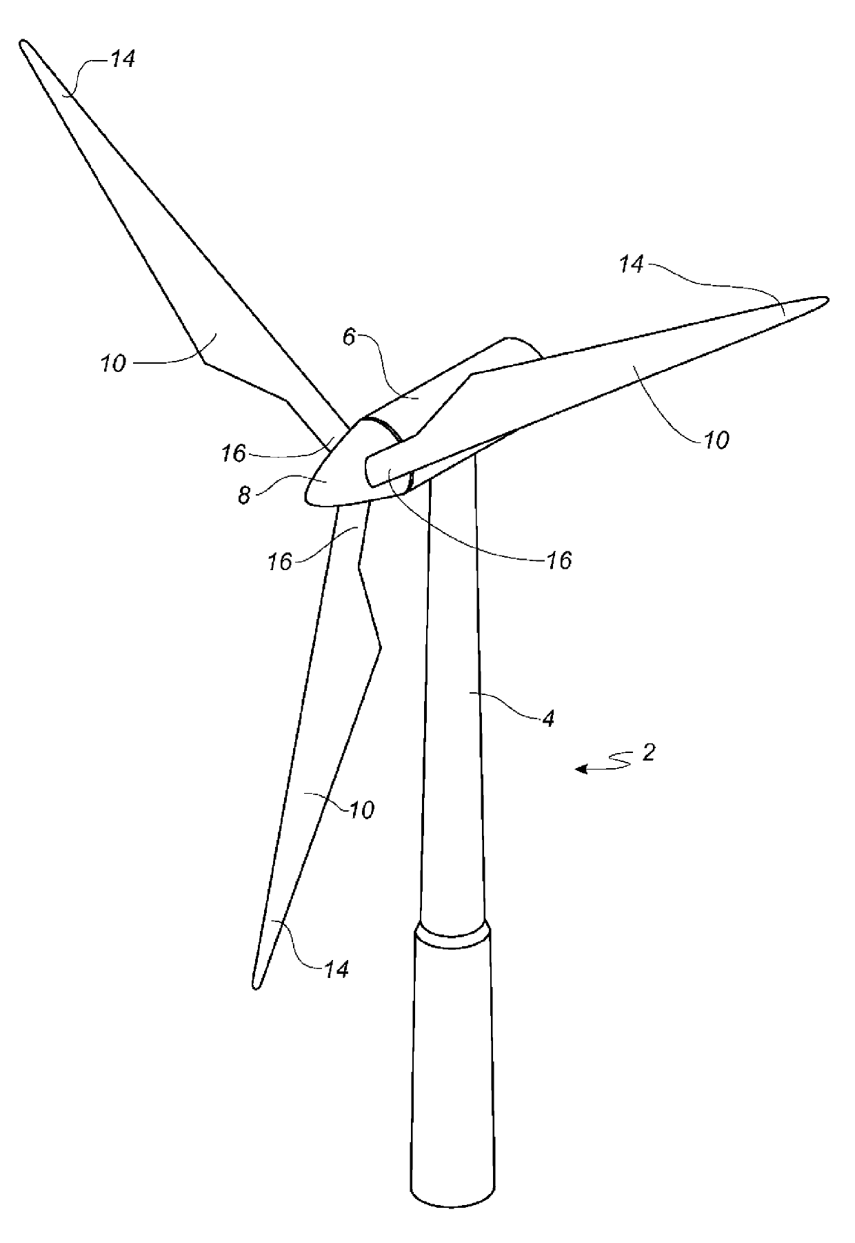
[0051] figure 1 A conventional modern upwind wind turbine according to the so-called "Danish concept" is shown with a tower 4, a nacelle 6 and a rotor with a substantially horizontal rotor shaft. The rotor comprises a hub 8 and three blades 10 extending radially from the hub 8 , each blade 10 having a blade root 16 closest to the hub and a blade tip 14 furthest from the hub 8 .

[0052] figure 2 A schematic view of a first embodiment of a wind turbine blade 10 according to the invention is shown. The wind turbine blade 10 has the shape of a conventional wind turbine blade, including a root region 30 closest to the hub, an airfoil or airfoil region 34 furthest from the hub, and a transition region between the root region 30 and the airfoil region 34 32. The blade 10 comprises a leading edge 18 facing the direction of rotation of the blade 10 when the blade is mounted on the hub and a trailing edge 20 facing in the opposite direction of the leading edge 18 .

[0053] The ai...


PUM


Abstract

A method of manufacturing a longitudinally extending composite structure including a shell part comprising a fibre reinforced polymer material including a polymer matrix and fibre material embedded in the polymer material is described. The shell part is manufactured in a closed mould comprising at least a first outer mould part (110) having a first forming surface (112) and a second outer mould part (210) having a second forming surface (212). The method comprises the steps of : a) arranging a first fibre material in the first forming surface of the first outer mould part, b) arranging a pre-fabricated longitudinally extending reinforcement element (130), such as a beam or a web, on top of the first fibre material, the reinforcement element having a first side and a second side, and a first bonding surface and a second bonding surface, the reinforcement element being arranged so that the first bonding surface faces towards the first forming surface, c) arranging a second fibre material (252, 253, 270) in the second forming surface of the second outer mould part ( 210), d) sealing a polymer foil (276) above the second fibre material so as to retain the second fibre material against the second forming surface, e) closing the at least first outer mould part and the second outer mould part so as to form the closed mould, and so that the second bonding surface of the reinforcement element faces towards the second forming surface, f) forming a mould cavity by arranging a first vacuum bag (140) between the first outer mould part, the second outer mould part and the first side of the reinforcement element, and arranging a second vacuum bag (142) between the first outer mould part, the second outer mould part and the second side of the reinforcement element, g) evacuating the mould cavity, h) providing a resin in the mould cavity simultaneously with and/or subsequently to steps a) and c), and i) curing the resin in order to form the composite structure.

Description

technical field [0001] The present invention relates to a method of manufacturing a longitudinally extending composite structure comprising a shell portion comprising a fiber reinforced polymer material comprising a polymer matrix and embedded polymer A fibrous material of the material wherein the housing part is produced in a closed mold comprising at least a first outer mold part having a first forming surface and a second outer mold part having a second forming surface. Background technique [0002] Vacuum infusion or VARTM (Vacuum Assisted Resin Transfer Molding) is a method that is commonly used to manufacture composite structures such as wind turbine blades comprising a fibre-reinforced matrix material. During the manufacturing process, a liquid polymer, also known as resin, is filled into a mold cavity into which fiber material has been inserted beforehand, and a vacuum is created in the mold cavity, which draws in the polymer. Polymers can be thermosets or thermopla...

Claims


Application Information

Patent Timeline
IPC IPC(8): B29C70/34B29C70/44B29C70/48
CPCB29K2105/246B29L2031/085B29L2031/082B29D99/0028B29C70/48F03D1/065B29C70/467B29C70/542B29C70/543Y02E10/721B29C70/865Y02E10/72Y02P70/50
Inventor M.达尔E.F.汉森B.K.莫尔滕森P.格拉鲍
Owner LM GLASSFIBER
Why Eureka
Try Eureka