Gearbox

A technology of transmission and receiver, applied in the direction of vehicle gearbox, gear transmission, transmission element, etc., can solve the problems of driving, fuel consumption, power loss of transmission, utilization of lubrication, etc., to achieve efficient circulation, improve reliability, restrain The effect of power loss

Inactive Publication Date: 2012-05-16
AISIN AI CO LTD
View PDF6 Cites 16 Cited by
  • Summary
  • Abstract
  • Description
  • Claims
  • Application Information

AI Technical Summary

Problems solved by technology

[0004] However, in the tubular shape of the oil storage container disclosed in Patent Document 1, since the lubricating oil brought up by the rotation of the transmission gear flies so as to be perpendicular to the longitudinal direction of the oil storage container, It is difficult to recover the lubricating oil that passes above and below the oil storage container
Therefore, the required amount of lubricating oil cannot be collected by the oil storage container, and since it cannot be supplied sufficiently, there is a concern that the lubricating oil on the tooth surfaces of other transmission gears and inside each shaft will be insufficient.
In addition, since the total amount of lubricating oil brought up by the rotation of the transmission gear cannot be used for lubrication, the transmission gear does useless work, and the transmission loses power, which may have a great impact on the driving and fuel consumption of the vehicle.

Method used


Image

  • Gearbox
  • Gearbox
  • Gearbox

Examples


Embodiment Construction

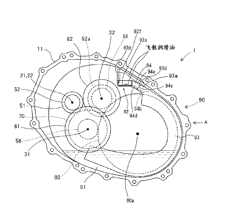
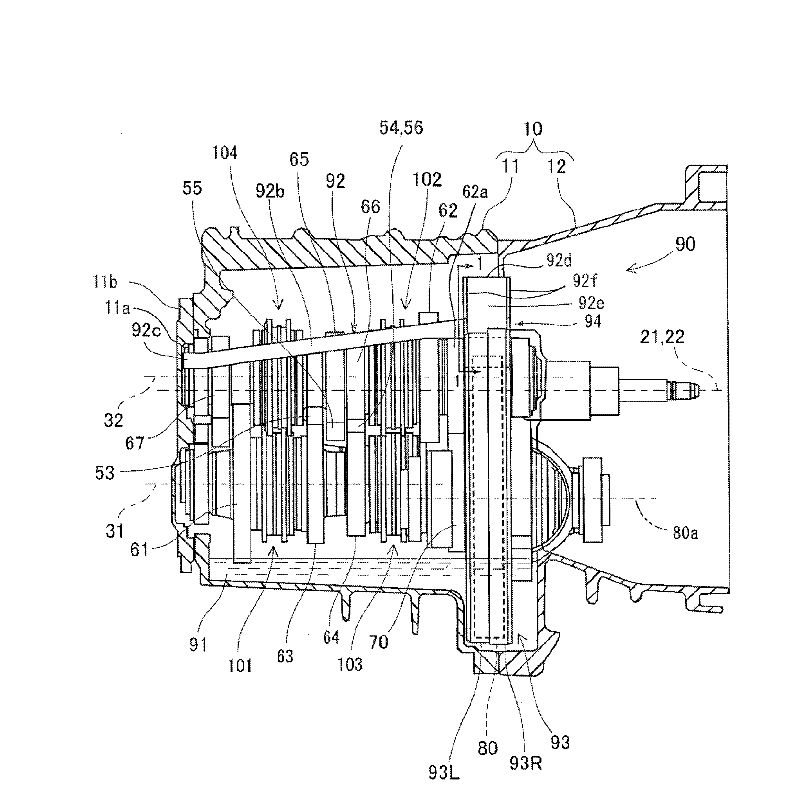
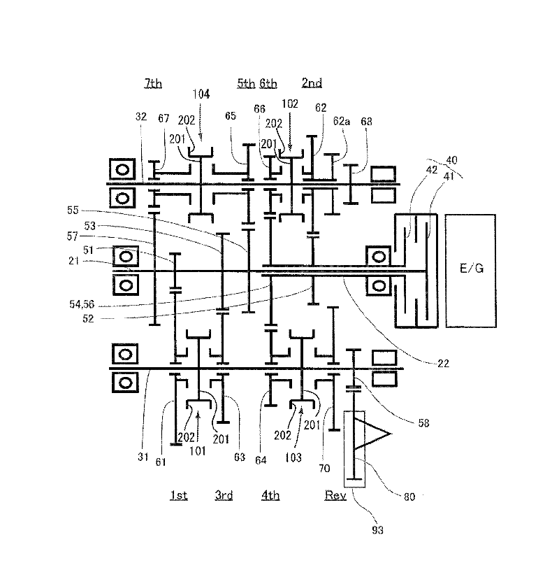
[0019] Below, refer to Figure 1 to Figure 4 The transmission 1 according to the first embodiment in which the present invention is embodied will be described. like Figure 1 to Figure 3 As shown, the transmission 1 is a dual-clutch automatic transmission, and includes a first input shaft 21 , a second input shaft 22 , a first output shaft 31 , and a second output shaft 32 as shaft bodies in the housing 10 . In addition, the housing 10 includes a dual clutch 40 , drive gears 51 to 57 for respective shift stages (corresponding to the “drive side gears” in the present invention), final reduction drive gears 58 and 68 , and driven gears 61 for respective shift stages. ~ 67 , the reverse gear 70 , the ring gear 80 (corresponding to the “large diameter gear” in the present invention), and the lubricating mechanism 90 . The final reduction drive gears 58 and 68, the driven gears 61 to 67, and the reverse gear 70 correspond to the "driven side gear" of the present invention.

[00...


PUM


Abstract

Provided is a gearbox provided with a lubrication structure wherein a lubricant that has been distributed can be efficiently supplied to each location to be lubricated, and the power loss is small. The gearbox is comprised of shaft bodies supported by a case (10) in the axial directions of the shaft bodies; a plurality of gears which are supported by the shaft bodies and which are rotatably coupled to the shaft bodies by a shift clutch; a large-diameter gear (80) among the plurality of gears, which has a lower portion immersed in a lubricant contained in a lubricant storage area (91) formed in the lower portion of the case (10) and which rotates to distribute the lubricant upwardly; and a receiver (92) which extends in a direction of the rotational axis of the large-diameter gear (80) to collect the distributed lubricant and circulate the lubricant to locations to be lubricated. The receiver (92) is comprised of a vertical wall (92d) having a surface on which the lubricant that has been distributed to disperse above the receiver impinges and moves downwardly, to introduce the lubricant to a collecting portion of the receiver, and an introduction portion (94) having a surface on which the lubricant that disperses between the receiver (92) and the large-diameter gear (80) flows due to the inertia force, to introduce the lubricant to a collecting portion (92a).

Description

technical field [0001] The present invention relates to a transmission lubricated so that lubricating oil is drawn up by a transmission gear. Background technique [0002] Conventionally, among vehicular transmissions that adjust the driving force and rotational speed of an internal combustion engine or the like, there is a transmission that is lubricated so that lubricating oil is drawn up by a transmission gear. For example, in the transmission disclosed in Patent Document 1, which discloses a lubricating mechanism for a transmission having an oil reservoir, lubricating oil picked up by a speed change gear is received by the oil reservoir and directed to the tooth surfaces of other speed change gears and the inside of each shaft. Supply lubricating oil. The oil storage container is arranged above the speed change gear, and has a bobbin shape with an upper opening. Furthermore, the lubricating oil which is carried up and scattered by the rotation of the transmission gear ...

Claims


Application Information

Patent Timeline
Patent Type & Authority Applications(China)
IPC IPC(8): F16H57/04F16H3/093
CPCF16H2003/0931F16H57/0494F16H2200/0056F16H57/0457F16H57/0423F16H57/0409F16H3/006Y10T74/19991F16H3/093F16H57/021F16H57/04
Inventor 川本全基粥川宪雄吉见拓也植松隼矢加藤博之尾神史朗
Owner AISIN AI CO LTD
Why Eureka
Try Eureka