Exhaust-gas aftertreatment device

A technology of exhaust gas post-treatment and internal combustion engine, which is applied in the direction of exhaust gas treatment, exhaust device, internal combustion piston engine, etc. It can solve the problems of not participating in the combustion process of the engine, and the capture material is easy to age, and achieve the effect of improved mixing

Active Publication Date: 2012-05-23
VOLVO CAR CORP
View PDF9 Cites 9 Cited by
  • Summary
  • Abstract
  • Description
  • Claims
  • Application Information

AI Technical Summary

Problems solved by technology

[0004] Also often problematic, especially during cold starts, is that liquid emissions in the exhaust emissions do not take part in the combustion process of the engine
However, capture materials are prone to aging

Method used


Image

  • Exhaust-gas aftertreatment device
  • Exhaust-gas aftertreatment device
  • Exhaust-gas aftertreatment device

Examples


Embodiment Construction

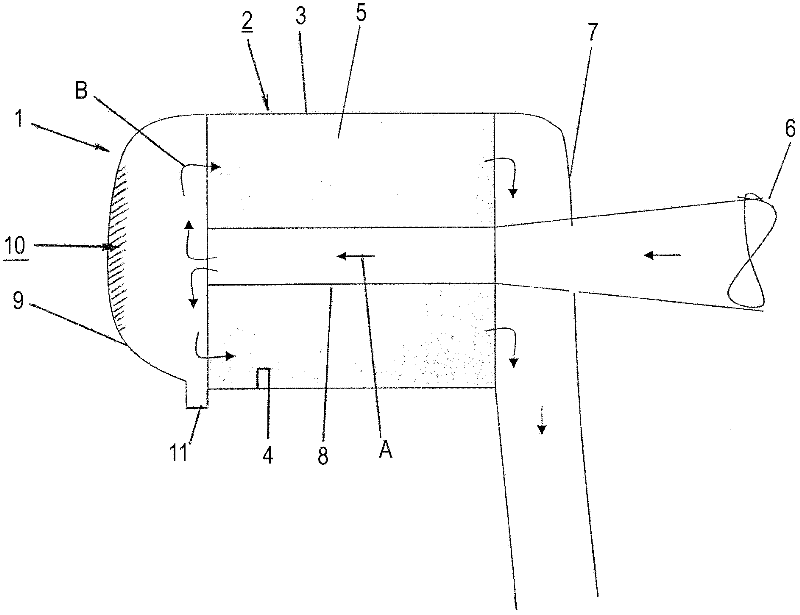
[0022] An exhaust gas aftertreatment device 1 according to the invention is provided for improving the catalytic conversion of exhaust emissions from an internal combustion engine (not shown). The internal combustion engine can be of any suitable type, such as is used in vehicles and other engine driven machinery.

[0023] as passed figure 1 It can be seen that the exhaust gas aftertreatment device 1 according to the invention is provided with a catalytic converter 2 which thus forms part of the device.

[0024] The catalytic converter 2 forming part of the device 1 may be of any suitable type and thus in figure 1 are shown schematically only. figure 1 The catalytic converter 2 shown in includes a tubular member 3 . This tubular member, which may be circular, square, rectangular or any other suitable shape in cross-section, defines a space 4 in which a catalytic converter substrate 5 of a suitable type is positioned. The space 4 in the tubular member 3 with the catalytic c...


PUM


Abstract

The present invention relates to an exhaust-gas aftertreatment device for an internal combustion engine, wherein said device (1) comprises a catalytic converter (2), wherein the catalytic converter (2) comprises a tubular member (3) which defines a volume (4) within which a catalytic converter substrate (5) is located, and wherein the volume (4) with the catalytic converter substrate (5) communicates with an inlet portion (6) for receiving exhaust gas emissions from the internal combustion engine and with an outlet portion (7) for discharging said exhaust gas emissions after catalytic conversion thereof in said volume. The device (1) comprises a pipe member (8) within said tubular member (3) of the catalytic converter (2), which pipe member connects the inlet portion (6) with the volume (4) in said tubular member (3) and guides the exhaust gas emissions from said inlet portion in a first direction of flow (A), and said pipe member (8) opens downstream into a deflector means (9) which deflects the exhaust gas emissions into the volume (4) of the tubular member (3) of the catalytic converter (2) in a second direction of flow (B) other than said first direction of flow (A) ( Fig. 1 ).

Description

technical field [0001] The invention relates to an exhaust gas aftertreatment device for improving the catalytic conversion of exhaust emissions from internal combustion engines, in particular during cold start and warm-up. The catalytic converter forming part of the device comprises a tubular member defining a space in which the catalytic converter base is disposed. The space with the catalytic converter base communicates with an inlet portion for receiving exhaust emissions from the internal combustion engine and with an outlet portion for discharging said exhaust emissions catalytically converted in said space. Background technique [0002] Catalytic converters for vehicles generally include a canned and coated catalytic converter substrate in communication with inlet and outlet passages. It is located on the exhaust side of the vehicle's internal combustion engine to treat exhaust emissions from the internal combustion engine. [0003] During cold starts and warm-ups o...

Claims


Application Information

Patent Timeline
Patent Type & Authority Applications(China)
IPC IPC(8): F01N13/00F01N5/02F01N3/28
CPCF01N3/2006F01N3/2803F01N1/084F01N2470/22F01N3/005Y02T10/26F01N2240/20F01N3/2013Y02T10/12
Inventor 马茨·劳莱尔扬·达尔格伦斯塔凡·奥弗松
Owner VOLVO CAR CORP
Why Eureka
Try Eureka