
Hydraulic pressure test device and method for explosion-proof part

A technology of hydraulic testing and pressure-holding devices, applied in the direction of measuring devices, applying stable tension/pressure to test material strength, instruments, etc., can solve inconvenient operation, low efficiency, increase production cycle of explosion-proof valve electric devices, etc. Problems, to achieve the effect of improving efficiency and accuracy

Inactive Publication Date: 2012-05-23
YANGZHOU ELECTRIC POWER EQUIP MFG FACTORY CO LTD
View PDF3 Cites 5 Cited by
  • Summary
  • Abstract
  • Description
  • Claims
  • Application Information

AI Technical Summary

Problems solved by technology

[0002] With the development of my country's electric power, coal, petroleum and other energy industries, the demand for valve electric devices with explosion-proof requirements is increasing, that is, there are more and more explosion-proof parts that require explosion-proof tests. The explosion test adopts a simple hydraulic test device. Use eyes to observe whether there is water leakage on the surface of the workpiece to judge whether the part is qualified or not. The existing device is inconvenient to operate and the efficiency is not high. For some larger workpieces, it is difficult to operate. It is even more difficult, which greatly reduces the efficiency of the explosion-proof parts test, thereby increasing the production cycle of the explosion-proof valve electric device

Method used


Image

  • Hydraulic pressure test device and method for explosion-proof part
  • Hydraulic pressure test device and method for explosion-proof part

Examples


Embodiment Construction

[0021] The present invention will now be described in further detail in conjunction with the accompanying drawings and preferred embodiments. These drawings are all simplified schematic diagrams, and only illustrate the basic structure of the present invention in a schematic manner, so they only show the configurations related to the present invention.

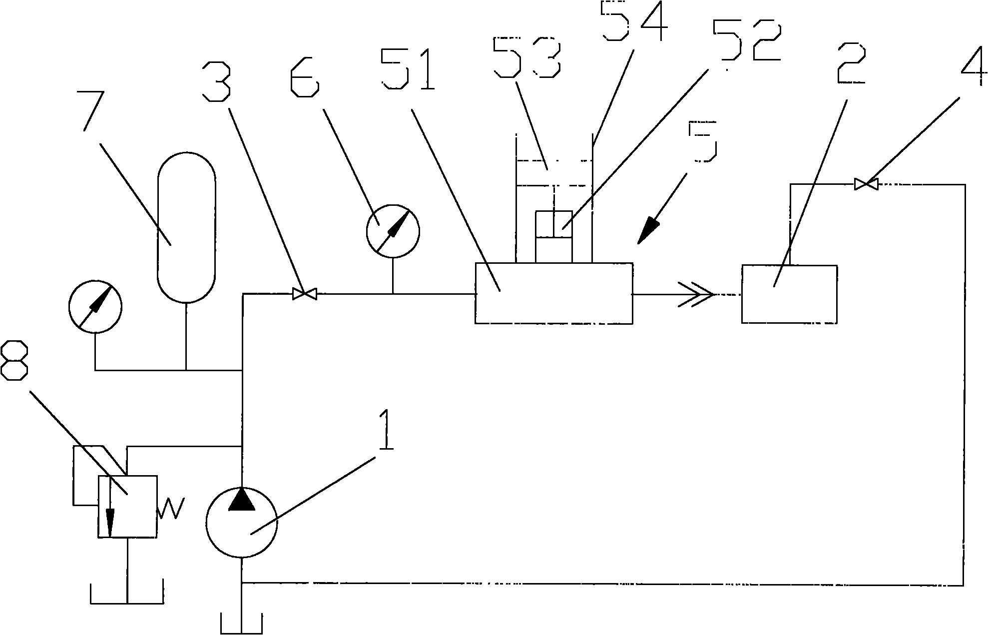
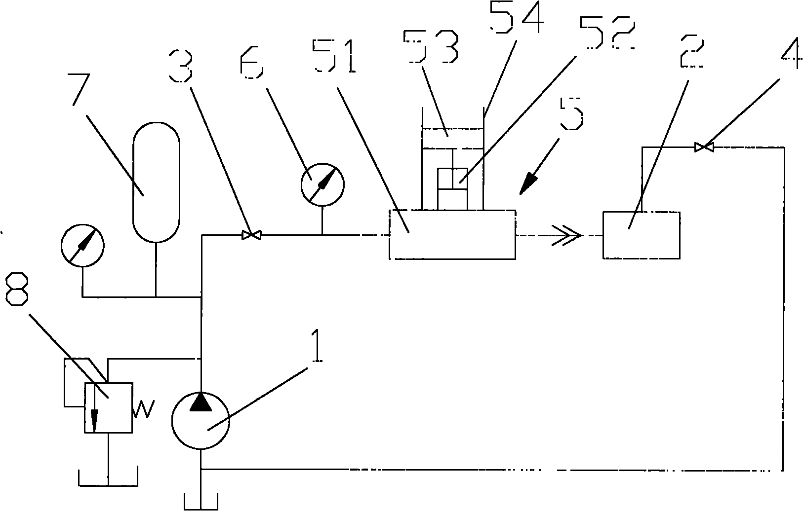
[0022] like figure 1 As shown, a hydraulic test device for explosion-proof parts, including a hydraulic pump 1 and a tested part 2, the two sides of the tested part 2 are provided with a water inlet valve 3 and a water outlet valve 4, the hydraulic pump 1, the tested part 2, the inlet The water valve 3 and the water outlet valve 4 are connected through pipelines, and a pressure maintaining device 5 is arranged on the pipelines of the water inlet valve 3 and the water outlet valve 4 . Test whether the tested part 2 is sealed by means of the pressure holding device 5 .

[0023] In order to further improve the test efficiency, ...


PUM


Abstract

The invention relates to a hydraulic pressure test device for an explosion-proof part. The device comprises a hydraulic pump and a part to be tested; an inlet valve and an outlet valve are respectively arranged at two sides of the part to be tested, the hydraulic pump, the part to be tested, the inlet valve and the outlet valve are connected through pipelines, and a pipeline between the inlet valve and the outlet valve is provided with a pressurizer. A testing method comprises the following operational steps: opening the hydraulic pump so as to allow water to enter and closing the outlet valve when water current at a water outlet of the part to be tested is stable; applying a set pressure, closing the inlet valve and pressurizing the part to be tested by using the pressurizer; determining that the part to be tested is defective if an alarm device sounds an alarm, determining that the part to be tested is qualified if the alarm device has no response and opening the outlet valve so as to finish testing. According to the invention, explosion and leakage in an explosion-proof test are specifically quantilized and directly represented; a conventional method of determining whether a part is in accordance with explosion-proof requirements by observing whether there are water drops around a workpiece in a conventional explosion-proof test is replaced; the efficiency rate and accuracy of the test are greatly improved.

Description

technical field [0001] The invention relates to the field of explosion-proof test of box parts, in particular to a hydraulic test device and method for explosion-proof parts. Background technique [0002] With the development of my country's electric power, coal, petroleum and other energy industries, the demand for valve electric devices with explosion-proof requirements is increasing, that is, there are more and more explosion-proof parts that require explosion-proof tests. The explosion test adopts a simple hydraulic test device. Use eyes to observe whether there is water leakage on the surface of the workpiece to judge whether the part is qualified or not. The existing device is inconvenient to operate and the efficiency is not high. For some larger workpieces, it is difficult to operate. It is even more difficult, which greatly reduces the efficiency of the explosion-proof parts test, thereby increasing the production cycle of the explosion-proof valve electric device. ...

Claims


Application Information

Patent Timeline
IPC IPC(8): G01N3/12G01N3/02
Inventor 樊高鹏李磊
Owner YANGZHOU ELECTRIC POWER EQUIP MFG FACTORY CO LTD
Learn More