Protection assembly

A component and substrate technology, applied in the field of protection components, can solve problems such as failure of the protection component 20, failure to protect charging devices or batteries, etc.

Active Publication Date: 2012-05-23
CYNTEC
View PDF5 Cites 5 Cited by
  • Summary
  • Abstract
  • Description
  • Claims
  • Application Information

AI Technical Summary

Problems solved by technology

When the protective component 20 is adhered to the circuit board by the reflow soldering process, the high temperature exceeding 200 degrees Celsius will cause the flux 26 to vaporize or displace instantly, so that the low-melting-point metal layer 23 cannot be actually encountered. Effective fusing during current or overvoltage, resulting in failure of the protection component 20, unable to protect the charging device or battery

Method used


Image

  • Protection assembly
  • Protection assembly
  • Protection assembly

Examples


Embodiment Construction

[0027] Below in conjunction with accompanying drawing, structural principle and working principle of the present invention are specifically described:

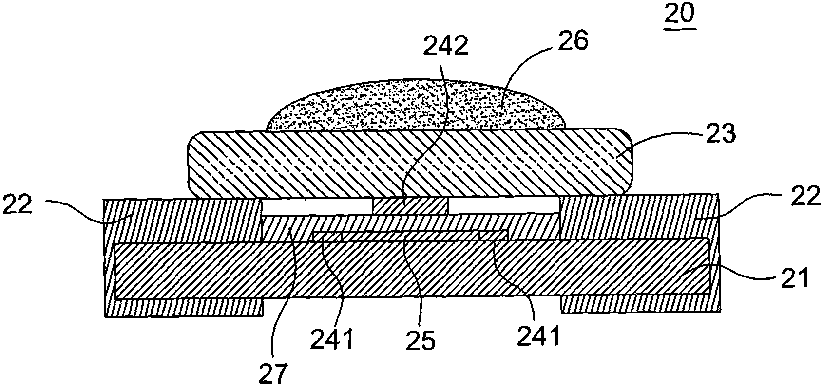
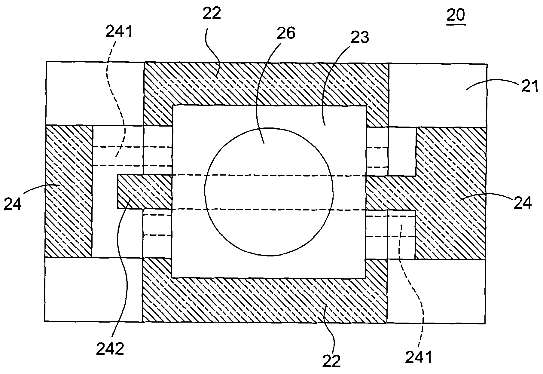
[0028] like Figure 4 Shown is a cross-sectional view of the protection assembly 30 of the first preferred embodiment of the present invention. In this embodiment, the protection component 30 can be a surface mount electronic component, which can be mounted on a circuit board through a reflow process. The protection component 30 includes a substrate 31 at its core. The substrate 31 is made of insulating material and is roughly rectangular. Specifically, suitable materials for the substrate 31 include inorganic materials such as ceramics (such as alumina), zirconia, silicon nitride, aluminum nitride, and boron nitride, or plastics, glass epoxy resin, and the like. For practical applications, inorganic materials are especially preferred.

[0029] Above the substrate 31, the protection component 30 includes two first electrod...


PUM


Abstract

A protection assembly comprises: a substrate, two first electrodes, a metal layer with a low melting point and an auxiliary layer. The first electrodes are arranged on two opposite sides of the substrate respectively. The metal layer with the low melting point is arranged on the first electrodes. The auxiliary layer is formed on the metal layer with the low melting point. A liquid phase point temperature of the auxiliary layer is lower than the liquid phase point temperature of the metal layer with the low melting point. And the liquid phase point temperature of the auxiliary layer is not lower than the temperature which is obtained by subtracting 25 degree from a maximum temperature of a reflow soldering technology. In the prior art, scaling powder has a gasification or shift problem in the reflow soldering technology. By using the protection assembly of the invention, the above problem can be solved. When the protection assembly encounters an overcurrent or an overvoltage, a charging device or a battery can be effectively protected.

Description

technical field [0001] The invention relates to an electronic component, in particular to a protection component capable of protecting an electronic device from being damaged by overcurrent or overvoltage. Background technique [0002] In order to protect the charging device and the battery from over-current or over-voltage damage during charging, a protection component is often installed in the charging device, so that when an over-current or over-voltage is encountered, an open circuit can be formed immediately and real-time protection The electronic components or batteries of the charging unit are not damaged. [0003] like figure 1 Shown is a schematic circuit diagram of a charging device. The overcurrent / overvoltage protection circuit 10 of the charging device has a protection component 11 . The protection component 11 is provided with current fuses 111 , 112 made of low-melting-point metal between the contact A and the contact B thereof. Once the current fuses 111 ...

Claims


Application Information

Patent Timeline
Patent Type & Authority Applications(China)
IPC IPC(8): H02H7/18H02H7/20
Inventor 陈国枢王钟雄
Owner CYNTEC
Why Eureka
Try Eureka