Phase-locked loop

A technology of phase-locked loop and phase detector, which is applied to the automatic control of power, electrical components, etc., and can solve the problem of prolonged locking time of the loop 20

Active Publication Date: 2012-05-23
MEDIATEK INC
View PDF3 Cites 4 Cited by
  • Summary
  • Abstract
  • Description
  • Claims
  • Application Information

AI Technical Summary

Problems solved by technology

Although this structure does not have the problem of high surge energy of the first type phase-locked loop, the speed of charging / discharging the capacitor C1 by the second charge pump 22B will directly limit the locking speed of the loop 20
In addition, this damping phenomenon also results in a longer lock-up time required for the circuit 20

Method used


Image

  • Phase-locked loop
  • Phase-locked loop
  • Phase-locked loop

Examples


Embodiment Construction

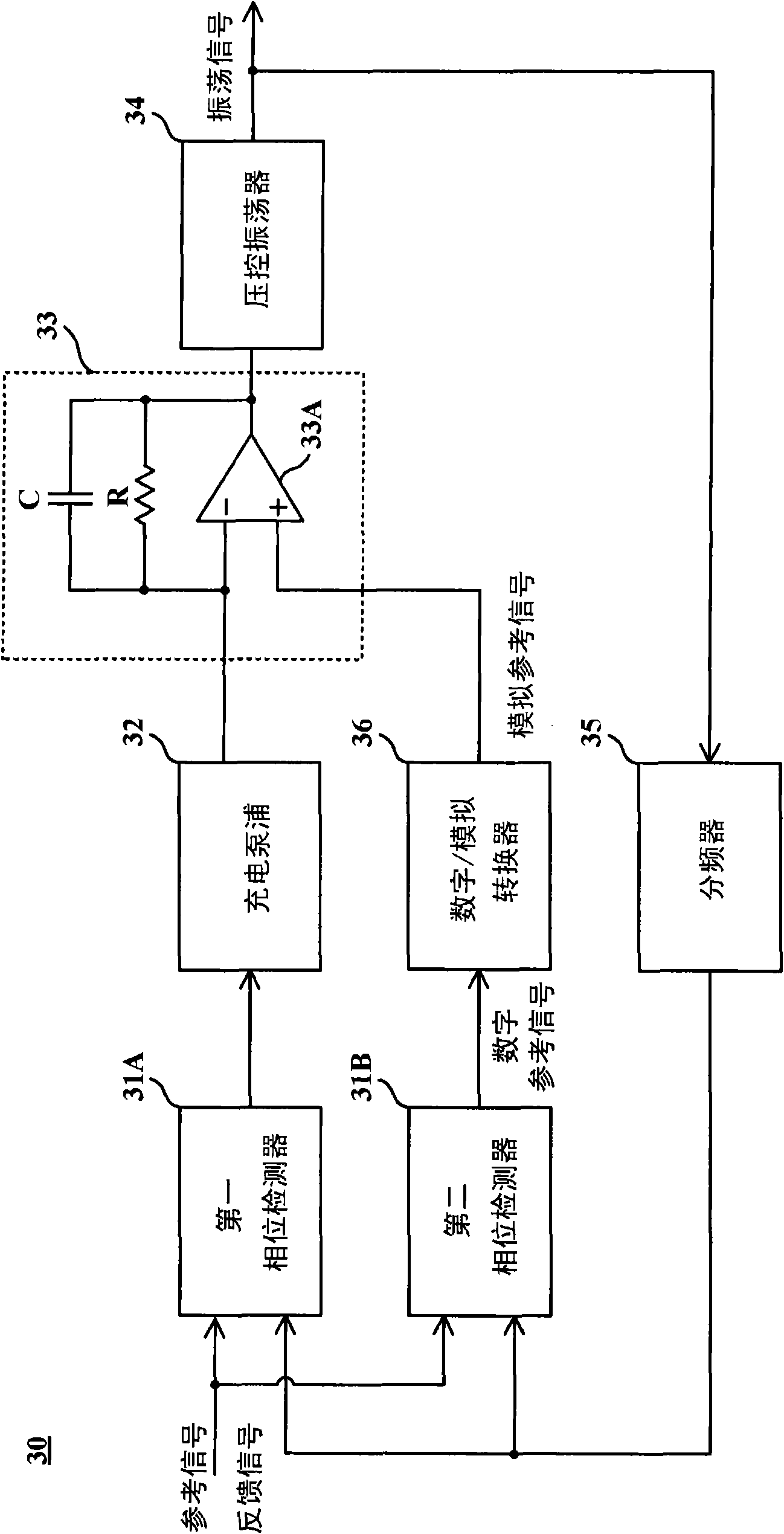
[0031] According to the first specific embodiment of the present invention is image 3 The phase-locked loop is shown. This loop 30 includes two-phase detectors 31A and 31B, a charge pump 32, an active filter 33 made up of a resistor R, a capacitor C, and an operational amplifier 33A, a voltage-controlled oscillator 34, a frequency divider 35, and a Digital / Analog Converter 36.

[0032] Such as image 3 As shown, the active filter 33 includes a first input terminal connected to the charge pump 32 , a second input terminal connected to the digital / analog converter 36 , and an output terminal for providing a control signal. The capacitor C and the resistor R are coupled in parallel between the first input terminal and the output terminal. The function of the voltage controlled oscillator 34 is to generate an oscillation signal according to the control signal. The frequency divider 35 is responsible for dividing the frequency of the oscillating signal to generate a feedback s...


PUM


Abstract

The invention provides a phase-locked loop. The phase-locked loop comprises an active filter, a voltage-controlled oscillator, two phase detectors, a charge pump and a digital/analogue converter, wherein the voltage-controlled oscillator generates an oscillation signal according to a control signal provided by the output end of the active filter; a first phase detector generates a phase difference signal according to a reference signal and a feedback signal corresponding to the oscillation signal; the charge pump provides a charging current to a first input end of the active filter according to the phase difference signal; a second phase detector generates a digital reference voltage according to the phase difference of the reference signal and the feedback signal; and the digital/analogue converter converts the digital reference voltage into an analogue reference voltage, and provides the analogue reference voltage to a second input end of the active filter.

Description

technical field [0001] The present invention relates to phase-locked loops, and in particular to the circuit architecture of phase-locked loops. Background technique [0002] In today's computer systems and communication systems, a phase-locked loop that can provide an oscillating signal with an accurate frequency plays an indispensable and important role. Taking the wireless communication system as an example, the transmitting end usually uses the oscillating signal generated by the phase-locked loop as the reference for sending the signal. The quality of the signal. [0003] figure 1 Shown is the structure diagram of the first type (type-I) phase-locked loop. The loop 10 includes a phase detector 11 , a charge pump 12 , a filter 13 composed of a resistor R and a capacitor C, a voltage-controlled oscillator 14 and a frequency divider 15 . Since the resistor R forms a leakage path between the input terminal of the voltage-controlled oscillator 14 and the ground terminal,...

Claims


Application Information

Patent Timeline
Patent Type & Authority Applications(China)
IPC IPC(8): H03L7/08H03L7/099
Inventor 谢明谕颜仕杰
Owner MEDIATEK INC
Why Eureka
Try Eureka