

Control cabinet body
A technology for controlling cabinets and cabinets, which is applied in the direction of circuit layout, cooling/ventilation/heating transformation on the support structure, etc., which can solve the problems of wasting manpower and material resources, reducing work efficiency, and wasting time, and achieves convenient maintenance and improved work efficiency. , the effect of easy operation
- Summary
- Abstract
- Description
- Claims
- Application Information
AI Technical Summary
Problems solved by technology
Method used
Image

Examples
Embodiment Construction
[0009] The present invention is described in further detail now in conjunction with accompanying drawing. These drawings are all simplified schematic diagrams, which only illustrate the basic structure of the present invention in a schematic manner, so they only show the configurations related to the present invention.
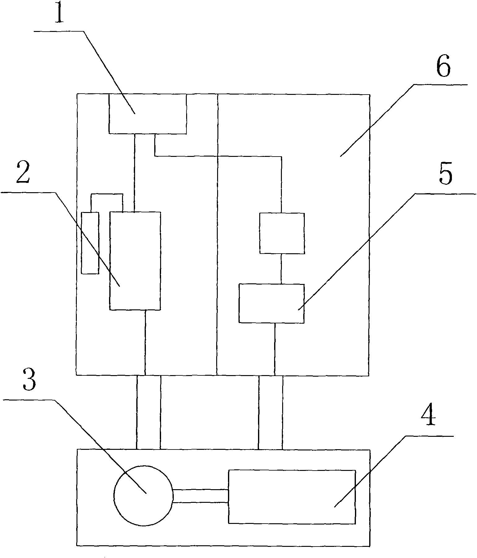
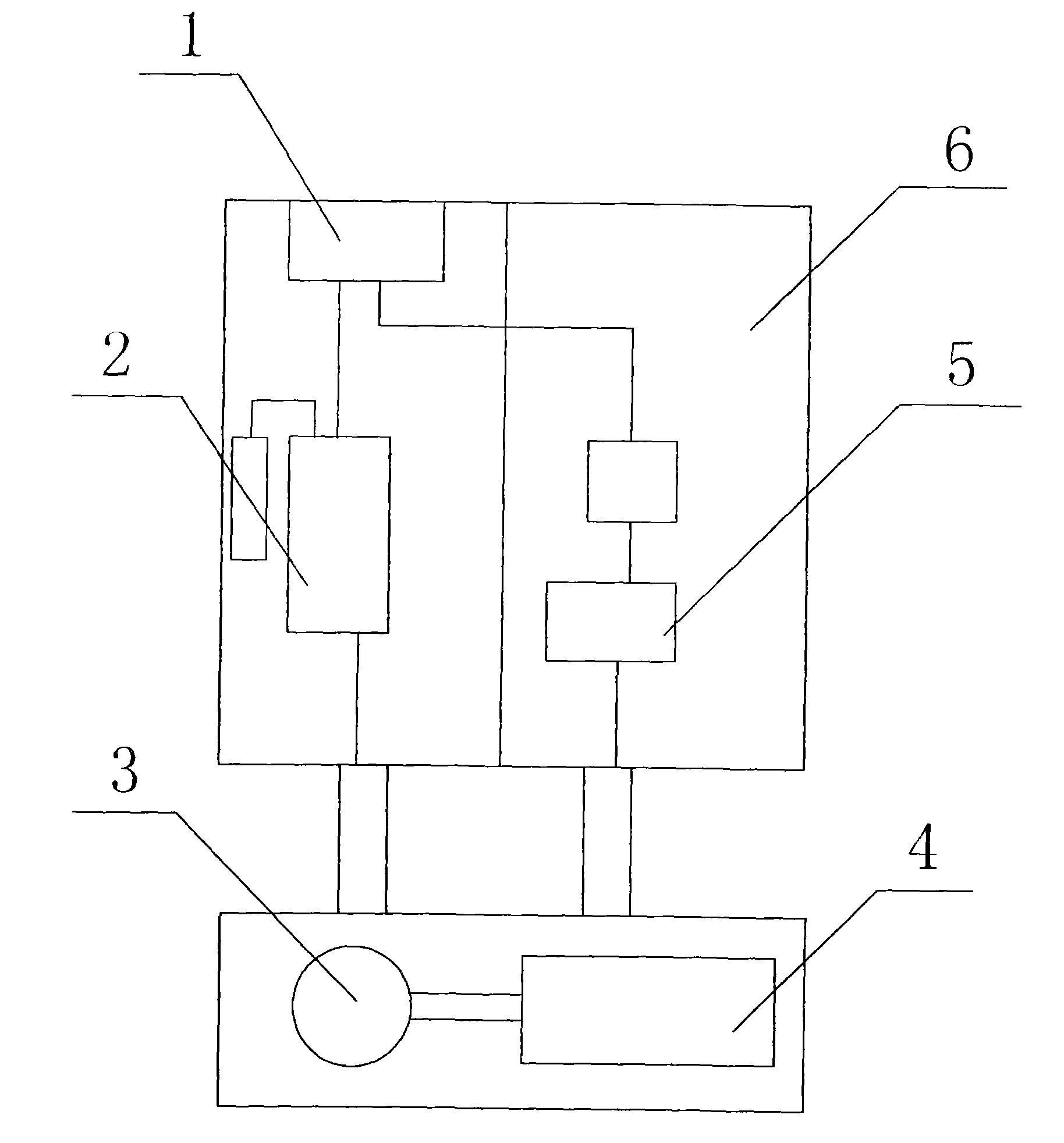
[0010] figure 1 It is a schematic diagram of the structure of the present invention, including a radiator 1, a braking unit 2, a motor 3, a mechanical device 4, a control detection system 5 and a cabinet 6, and the cabinet 6 is provided with a radiator 1, and the radiator 1 is connected to the system The moving unit 2 and the control detection system 5, the bottom of the cabinet 6 are provided with a motor 3 and a mechanical device 4, and the motor 3 is connected to the mechanical device 4.
[0011] The control cabinet of the present invention has the characteristics of simple structure, reasonable internal structure design, small size, light weight, easy ope...
PUM
 Abstract
Description
Claims
Application Information