Stacked piezoelectric element, injection device using same, and fuel injection system

A piezoelectric element and injection device technology, applied in the manufacture/assembly of piezoelectric/electrostrictive devices, charging systems, fuel injection devices, etc., can solve problems such as discharge, cracks, and insufficient heat resistance, and achieve Realize the effect of displacement and high displacement

Inactive Publication Date: 2012-05-23
KYOCERA CORP
View PDF4 Cites 8 Cited by
  • Summary
  • Abstract
  • Description
  • Claims
  • Application Information

AI Technical Summary

Problems solved by technology

[0005] However, when the multi-layer piezoelectric element is used as a piezoelectric actuator in a fuel injection device (injector) such as an internal combustion engine of an automobile, that is, when it is used under severe conditions such as continuous driving at high temperature, the resin For coating, the heat resistance is not necessarily sufficient, so there is a problem that discharge may occur between the internal electrode layers on the side of the laminated body
[0006] In addition, when it is considered that the multilayer piezoelectric element is used in water or chemicals, it is difficult for the resin to reliably prevent the intrusion of water or chemicals. The problem of discharge between
[0007] On the other hand, in order to avoid the above-mentioned problems, it is conceivable not to expose the internal electrode layer on the side of the laminated body, but in this case, there is a problem that when the laminated body of the multi-layer piezoelectric element is stretched, due to the applied The stress of the portion of the piezoelectric layer interposing the internal electrode layer, that is, the portion that is piezoelectrically inactive, causes a crack to occur between the piezoelectric layers of the laminate, and the crack propagates between the internal electrode layers, Causes a short circuit sometimes between the internal electrode layers of the positive and negative electrodes

Method used


Image

  • Stacked piezoelectric element, injection device using same, and fuel injection system
  • Stacked piezoelectric element, injection device using same, and fuel injection system
  • Stacked piezoelectric element, injection device using same, and fuel injection system

Examples


Embodiment

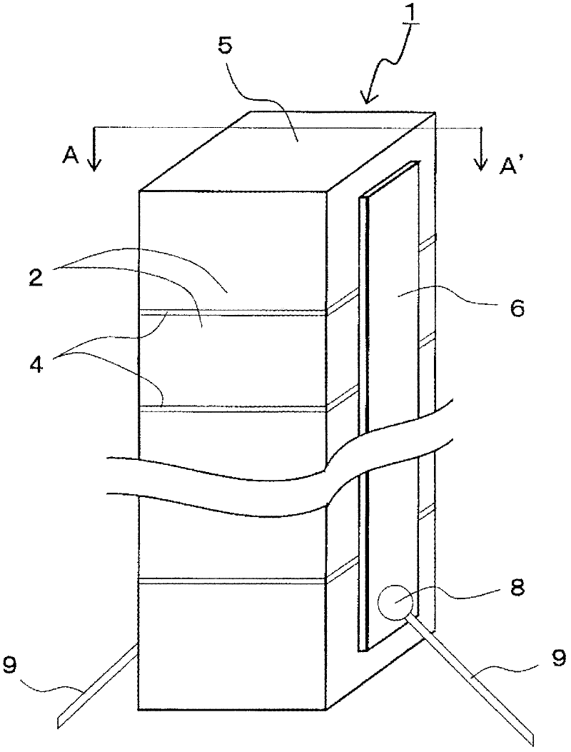
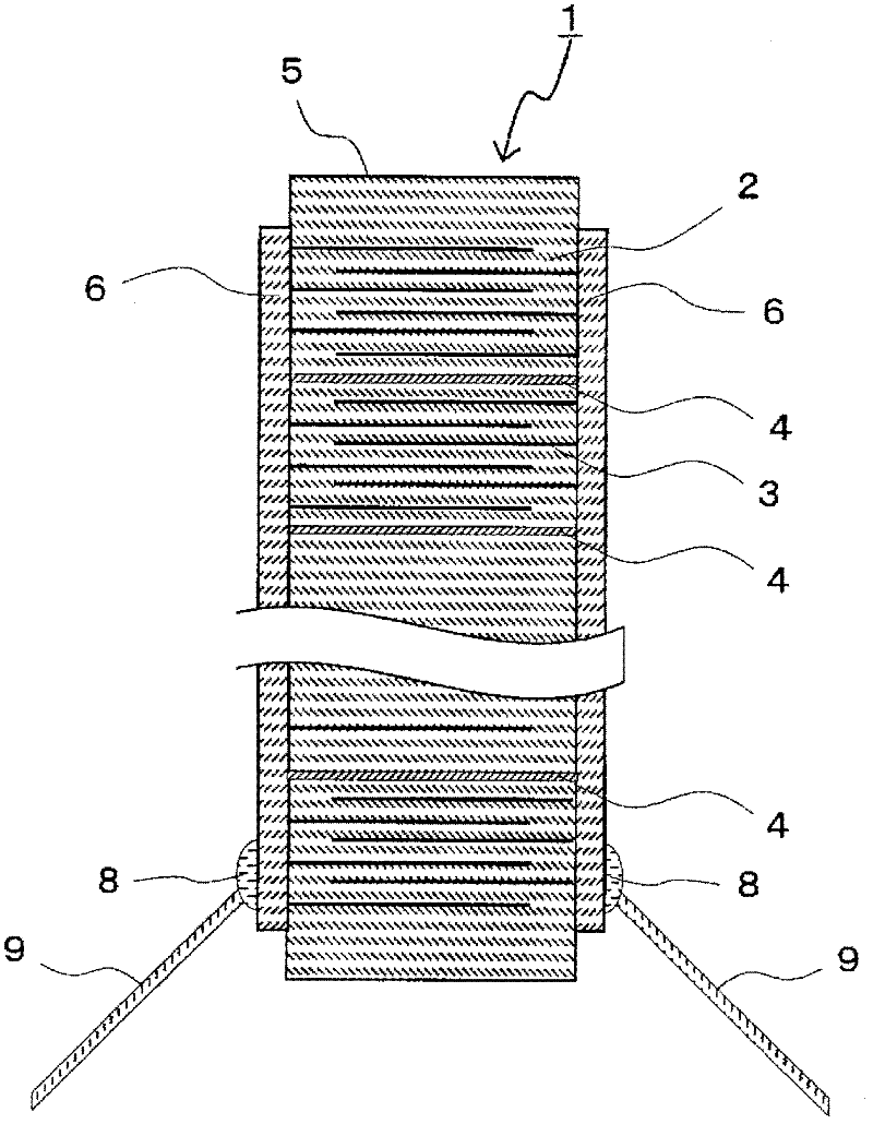
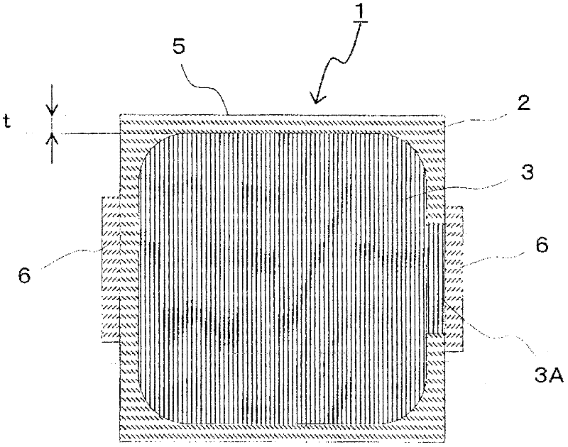
[0107] Embodiments of the multi-layer piezoelectric element of the present invention will be described below.

[0108] A piezoelectric actuator having the multi-layer piezoelectric element of the present invention was produced as follows. First, lead zirconate titanate (PZT: PbZrO 3 -PbTiO 3 ) is mainly composed of calcined powder of piezoelectric ceramics, a binder and a plasticizer to prepare a ceramic slurry. Using this ceramic slurry, a piezoelectric ceramic green sheet constituting a piezoelectric layer having a thickness of 100 μm was produced by the doctor blade method.

[0109] In addition, a binder was added to the silver-palladium alloy to prepare an internal electrode layer conductive paste (first conductive paste) constituting the internal electrode layer and the electrode lead-out portion. The silver-palladium ratio at this time was 95% by mass of silver-5% of palladium.

[0110] In addition, a binder was added to the silver-palladium alloy to prepare a stress...


PUM

PropertyMeasurementUnit
thicknessaaaaaaaaaa

Abstract

Conventional stacked piezoelectric elements sometimes cannot be stably driven because cracking sometimes occurs in a stack when the amount of displacement is large and when being driven at high speed. Specifically provided is a stacked piezoelectric element (1), the stacked piezoelectric element (1) comprising: a stack (5) in which piezoelectric layers (2) and internal electrode layers are alternately stacked and stress relaxation layers (4) are disposed between some of the piezoelectric layers (2); and external electrodes (6) joined to side surfaces of the stack (5) and electrically connected to the internal electrode layers, wherein the internal electrode layers are not exposed on the side surfaces of the stack (5), and the stress relaxation layers (4) are exposed on the side surfaces of the stack (5). The stacked piezoelectric element (1) with excellent durability can be provided in which cracking that occurs due to stress caused by the expansion and contraction of the stack (5) can be selectively caused to occur from the stress relaxation layer (4) so that the stress can be relaxed to thereby prevent the occurrence of a short circuit between the internal electrode layers caused by cracking and achieve high displacement.

Description

technical field [0001] The present invention relates to a multilayer piezoelectric element used as, for example, a piezoelectric drive element (piezoelectric actuator), a pressure sensor element, a piezoelectric circuit element, and the like. Background technique [0002] A conventional multilayer piezoelectric element includes, for example: a laminate in which piezoelectric layers and internal electrode layers are alternately laminated; a pair of external electrodes bonded to the side surfaces of the laminate and electrically connected to the internal electrode layer. They are set so as to have different polarities alternately, and are respectively led out to the side surfaces of the laminated body. [0003] On the side surface of the laminated body where no external electrodes are formed, the internal electrode layer set so as to increase the area as much as possible across the piezoelectric layer may be exposed. In this case, in order to prevent discharge on the side surf...

Claims


Application Information

Patent Timeline
Patent Type & Authority Applications(China)
IPC IPC(8): H01L41/083F02M51/06H01L41/187H01L41/22H02N2/00H01L41/273
CPCF02M51/0603H01L41/0838F02M63/0225H01L41/273Y10T29/42H10N30/872H10N30/508H10N30/053
Inventor 中村成信
Owner KYOCERA CORP
Why Eureka
Try Eureka