Ultrasonic bone knife head

A bone knife and ultrasonic technology, applied in the field of medical devices, can solve the problems of poor load capacity, low service life, high production cost, etc., and achieve the effect of reducing processing difficulty, fast speed, and exquisite and compact knife head

Active Publication Date: 2014-07-09
JIANGSU SMTP TECH CO LTD
View PDF10 Cites 1 Cited by
  • Summary
  • Abstract
  • Description
  • Claims
  • Application Information

AI Technical Summary

Problems solved by technology

[0003] This ultrasonic bone knife head has the following problems: slow cutting speed, low efficiency, poor load capacity, waste of energy; easy to break, low service life; complex shape, high processing difficulty, high production cost

Method used


Image

  • Ultrasonic bone knife head
  • Ultrasonic bone knife head
  • Ultrasonic bone knife head

Examples


Embodiment Construction

[0021] The technical solutions of the present invention will be further described below in conjunction with the accompanying drawings and through specific implementation methods.

[0022] The main idea of ​​the technical solution of the present invention is that in the structural shape of the ultrasonic bone knife head, the knife tip is located on the central axis of the entire knife head, so that all the energy generated by the ultrasonic transducer is concentrated on the knife tip of the ultrasonic bone knife head The part (the most effective working part) converges into one point, so that the tip of the cutter head has the strongest energy output and achieves the strongest working effect.

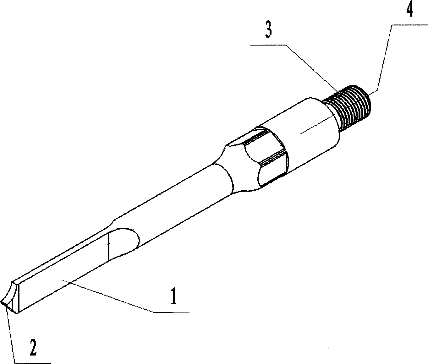
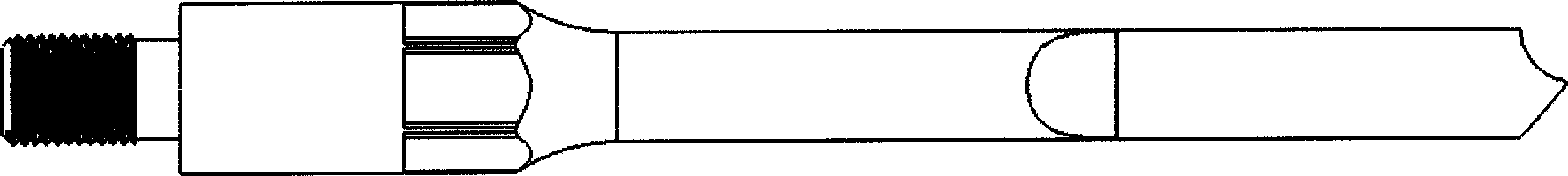
[0023] figure 2 It is a structural schematic diagram of the ultrasonic osteotome cutter head in Embodiment 1 of the present invention. image 3 It is a schematic side view of the ultrasonic osteotome head in Embodiment 1 of the present invention. Such as figure 2 and image 3 As sh...


PUM


Abstract

The invention discloses an ultrasonic bone knife head. The ultrasonic bone knife head comprises a blade and a knife tip, wherein the knife tip is positioned at the front end of the blade and is used for converging all the energy of an ultrasonic bone knife to the knife tip part. Due to the adoption of the technical scheme provided by the invention, the cutting speed can be increased, the operation time is reduced, and the cutting degree and the cutting shape of a bone can be precisely controlled.

Description

technical field [0001] The invention relates to the technical field of medical instruments, in particular to an ultrasonic osteotome cutter head. Background technique [0002] In orthopedic surgery, ultrasonic osteotome is often used for cutting, grinding, planing, scraping or arbitrary shaping of bone. Such as figure 1 It can be seen that the current ultrasonic osteotome has multiple teeth and a wide blade tip, and most of the blade tip is not the effective main cutting site. [0003] The ultrasonic bone knife head has the following problems: slow cutting speed, low efficiency, poor load capacity, waste of energy; easy to break, low service life; complex shape, high processing difficulty, and high production cost. Contents of the invention [0004] The purpose of the present invention is to provide an ultrasonic osteotome cutter head, which can increase the cutting speed, reduce the operation time, and can precisely control the cutting amount and shape of the bone. [...

Claims


Application Information

Patent Timeline
Patent Type & Authority Patents(China)
IPC IPC(8): A61B17/3209
Inventor 不公告发明人
Owner JIANGSU SMTP TECH CO LTD
Why Eureka
Try Eureka