Continuous dynamic countercurrent extracting process for effective component of plants
A technology for dynamic extraction of plant active ingredients, applied in solid solvent extraction and other directions, can solve the problems of low production capacity and production efficiency, low extraction rate of active ingredients, and large equipment footprint, so as to improve the degree of automation and reduce equipment occupation. Land area, the effect of reducing consumption
- Summary
- Abstract
- Description
- Claims
- Application Information
AI Technical Summary
Problems solved by technology
Method used
Image
Examples
specific Embodiment approach 1
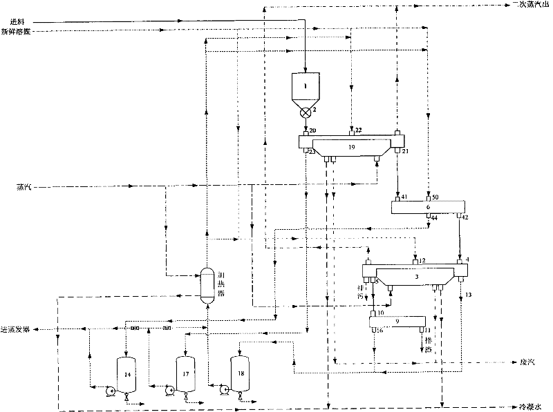
[0013] Specific implementation mode one: refer to figure 1 , the specific embodiment adopts the following technical scheme: it comprises a metering silo 1, a countercurrent dynamic extractor 3, a squeeze extractor 6, a slag extruder 9, a first storage tank 14, a second storage tank 17, a third storage tank 18 Prepreg 19, the discharge port 2 of the metering bin 1 is connected to the feed port 20 of the prepreg 19 through a pipeline, the discharge port 21 of the prepreg is connected to the feed port 41 of the extrusion extractor through a pipeline, and the extrusion The discharge port 42 of the pressure extractor is connected to the feed port 4 of the countercurrent dynamic extractor through a pipeline, the countercurrent dynamic extractor 3 is provided with a countercurrent dynamic extractor discharge port 5, and the prepreg 19 is provided with a solvent inlet 22 , the squeeze extractor 6 is provided with a squeeze extractor solvent inlet 50, the countercurrent dynamic extract...
specific Embodiment approach 2
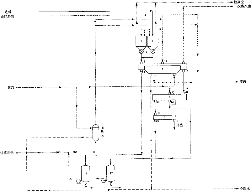
[0019] Specific implementation mode two: refer to figure 2 , The difference between this specific embodiment and the specific embodiment one is that it comprises a metering silo 1, a countercurrent dynamic extractor 3, an extruding extractor 6, a first storage tank 14 and a second storage tank 17, and the metering silo The discharge port 2 is connected to the feed port 4 of the countercurrent dynamic extractor through a pipeline, the discharge port 5 of the countercurrent dynamic extractor is connected to the feed port 41 of the squeeze extractor through a pipeline, and the squeeze extractor 6 is provided with a squeeze extractor Outlet 42, the countercurrent dynamic extractor 3 is provided with a countercurrent dynamic extractor solvent inlet 12, the squeeze extractor 6 is provided with a squeeze extractor solvent inlet 50, and the countercurrent dynamic extractor extraction liquid outlet 13 is connected to the first The storage tank 14 is connected, and the extraction liqui...
specific Embodiment approach 3
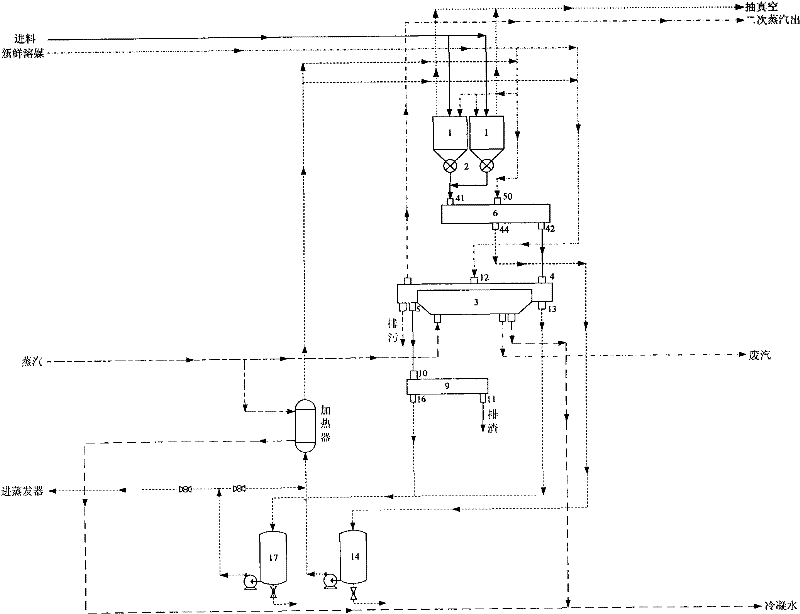
[0020] Specific implementation mode three: refer to image 3 The difference between this specific embodiment and the second specific embodiment is: the discharge port 2 of the metering silo is connected to the feed port 41 of the extrusion extractor through a pipeline, and the discharge port 42 of the squeeze extractor is connected to the discharge port 42 through a pipeline. The countercurrent dynamic extractor feed port 4 is connected, the countercurrent dynamic extractor 3 is provided with a countercurrent dynamic extractor outlet 5, the extrusion extractor 6 is provided with a squeeze extractor solvent inlet 50, and the countercurrent dynamic extractor 3 is provided with a There is a countercurrent dynamic extractor solvent inlet 12, and the extraction solution outlet 44 of the squeeze extractor is connected with the first storage tank 14 through a pipeline, and the countercurrent dynamic extractor extraction solution outlet 13 is connected with the second storage tank 17 t...
PUM
 Abstract
Description
Claims
Application Information
 - R&D Engineer
- R&D Manager
- IP Professional
- Industry Leading Data Capabilities
- Powerful AI technology
- Patent DNA Extraction
Browse by: Latest US Patents, China's latest patents, Technical Efficacy Thesaurus, Application Domain, Technology Topic, Popular Technical Reports.
© 2024 PatSnap. All rights reserved.Legal|Privacy policy|Modern Slavery Act Transparency Statement|Sitemap|About US| Contact US: help@patsnap.com


