Recycling device for residual fluid in fluid supply system/equipment and its use method

A fluid supply and fluid technology, applied in residential hot water supply systems, applications, piping systems, etc., can solve problems such as inability to recover branch pipes

Inactive Publication Date: 2015-06-24
吴星游
7 Cites 0 Cited by

AI-Extracted Technical Summary

Problems solved by technology

But it needs to change the original pipeline, and it can only recover the residual water in the main pipeline, but cannot recover the residual water ...

Method used

When the water heater is ready to supply hot water and the valves 24 and 20 are opened, the gas water heater starts to work, the water starts to flow, and the liquid flow switch is closed; but if the temperature of the water in the pipeline of the gas water heater water outlet 22 meets the When required, the bimetal temperature switch is disconnected, the water pump 5 does not start, and the water heater 21 normally supplies hot water that meets the requirements; if the temperature of the water in the pipeline does not meet the requirements and needs to be recycled, the bimetal temperature switch is closed, and the water pump 5 is started. Pump the water from the recy...

Abstract

A recycling device for residual fluid in a fluid supply system/equipment and its use method are disclosed. The recycling device includes an intake pipe (2) for introducing fluid, a drain pipe (3) for discharging fluid and a fluid conveying means (5) communicated with the intake pipe (2) and the drain pipe (3). At least one fluid state sensor is provided in or out of fluid pipelines, at least one fluid performance sensor is provided in or out of the pipelines of the outlet end of the fluid supply system/equipment. By way of opening the supply valve of the fluid supply system/equipment, fluid in the fluid supply system/equipment that does not meet specific requirements can be recycled and reused automatically, and the fluid meeting the requirements is supplied after finishing the recycling process.

Application Domain

Fluid heatersPipeline systems +1

Technology Topic

EngineeringFluid supply

Image

  • Recycling device for residual fluid in fluid supply system/equipment and its use method
  • Recycling device for residual fluid in fluid supply system/equipment and its use method
  • Recycling device for residual fluid in fluid supply system/equipment and its use method

Examples

  • Experimental program(10)

Example Embodiment

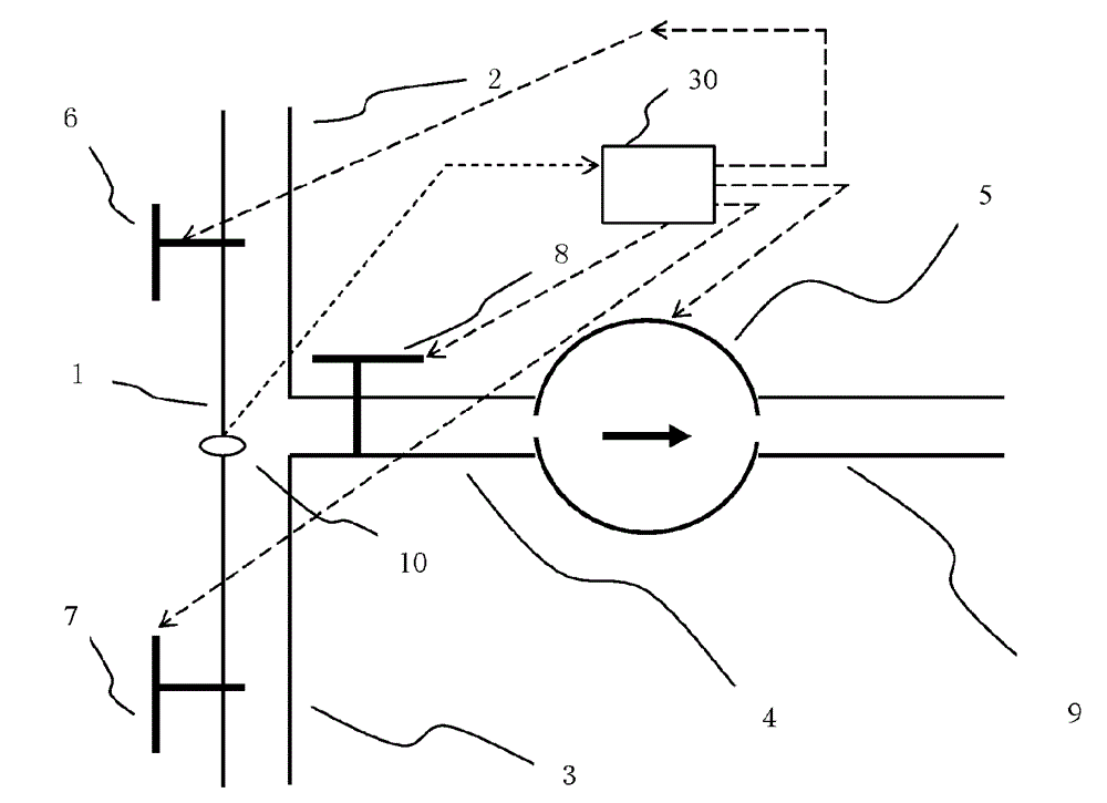
[0077] Example 1: A recycling device that uses a three-way pipe equipped with an electric two-way valve to control the flow of high-temperature (or low-temperature) liquid.
[0078] Such as figure 1 As shown, the recycling device includes a three-way structure 1 with a three-way pipe and an electric two-way valve. The three-way structure 1 connects the inlet pipe 2 with the high-temperature (or low-temperature) liquid supply system or the liquid inlet direction of the equipment. The pipes are connected, the outlet pipe 3 communicates with the pipe in the direction of the liquid supply system or the equipment, the outlet pipe 4 is connected to the liquid pump 5 and the outlet pipe 9 (the outlet pipe 9 can also be omitted), and the three-way structure 1 is provided with Inlet pipe electric two-way valve 6, outlet pipe electric two-way valve 7, extraction pipe electric two-way valve 8, a temperature sensor and a pressure sensor (not shown in the figure) are installed at position 10, the controller 30 and the sensor, The liquid pumps 5 are wired and electrically connected, and the signals from the sensors control the actions of the electric two-way valves 6, 7, 8 and the liquid pump 5 through the circuit of the controller 30. When the pressure in the pipeline is medium pressure or negative pressure, the recycling device is in working condition.
[0079] A common installation method is to install the device in the liquid outlet pipeline close to the liquid supply system or equipment, at this time the inlet pipe 2 of the device and the liquid outlet of the liquid supply system or equipment that have been processed Connected, the outlet pipe 3 of the device communicates with the user end of the liquid supply system or equipment. When the liquid in the pipeline is not flowing, the pressure is zero (the valve of the liquid supply system or equipment is not opened) or high pressure (the valve of the liquid supply system or equipment is opened but the valve on the user side is not opened), the recycling device does not enter the working state When the valve of the liquid supply system or equipment and the valve on the user side are both opened and the liquid in the pipeline starts to flow, the pressure becomes medium pressure, and the recycling device enters the working state; at this time, if the temperature sensor detects that the liquid in the pipeline meets the design When required, the electric valves 6 and 7 are kept open through the control circuit, and the electric valve 8 is kept closed. The liquid that meets the requirements normally passes through the inlet pipe 2, the electric valve 6, the three-way pipe, and the electric valve 7 of the recycling device. The outlet pipe 3 is sent to the user end; if the temperature sensor detects that the liquid in the pipeline does not meet the set requirements, close the electric valve 6 through the control circuit, open the electric valve 7 and the electric valve 8, and start the liquid pump 5 at the same time, then The liquid that does not meet the requirements in the pipeline from the recycling device to the user end is drawn out through the outlet pipe 3, electric valve 7, three-way pipe, electric valve 8, suction pipe 4, liquid pump 5, and outlet pipe 9, and the pressure is negative at this time; When the unqualified liquid in the pipeline from the recycling device to the user end is pumped, the pressure becomes a negative pressure close to zero, and the signal measured by the pressure sensor closes the electric valve 7 through the control circuit, and opens the electric valve 6 and the electric valve 8. The liquid pump 5 continues to work and pumps the unqualified liquid from the recycling device to the liquid supply system or the internal pipeline of the equipment through the inlet pipe 2, the electric valve 6, the three-way pipe, the electric valve 8, the extraction pipe 4, and the liquid pump 5 ( It can also rely on the pressure in the liquid supply system or the internal pipes of the equipment to keep the liquid moving and make the liquid flow out, without starting the liquid pump), and the fresh liquid enters the liquid supply system or equipment at the same time and is processed by the latter; when the temperature sensor measures the liquid When the supply system or equipment starts to flow out the liquid that meets the requirements, the recycling device returns to its normal state, and the liquid that meets the requirements can be delivered to the user through the recycling device. When the valve of the liquid supply system or equipment or the valve on the user side is closed, the liquid stops flowing, the pressure is zero or high pressure, and the recycling device exits the working state. A conductivity sensor can also be installed at position 10 to sense the state of the liquid being pumped out, and use the control circuit to extract the unqualified liquid from the recycling device to the liquid supply system or the internal pipeline of the equipment.
[0080] The extracted liquid can be discarded or used for washing items or for other purposes, or directly pressed into the storage container of a liquid supply system or equipment (such as a solar water heater) with a liquid storage container for reuse.
[0081] If the outlet pipe not only leads to the liquid storage container, but also communicates with the pipe at the liquid inlet end of the liquid supply system or equipment through a branch pipe, the branch pipe is provided with a branch pipe electric valve, and the outlet pipe is close to the liquid storage container. An export electric valve is provided at one end, and the electric valve is electrically connected with the control circuit. In this way, when the unqualified liquid in the pipeline from the recycling device to the user is pumped out, the liquid can be transported to the liquid storage container through the export electric valve. When the liquid in the pipeline from the recycling device to the liquid supply system or the equipment is extracted, it can be Send it directly into the liquid inlet pipe of the liquid supply system or equipment through the electric valve of the branch pipe, that is, let the liquid in the liquid supply system or the internal pipe of the equipment be recycled, when the temperature sensor measures the liquid in the pipe to meet the setting When requested, the recycling device will return to its normal state and supply the liquid that meets the requirements.

Example Embodiment

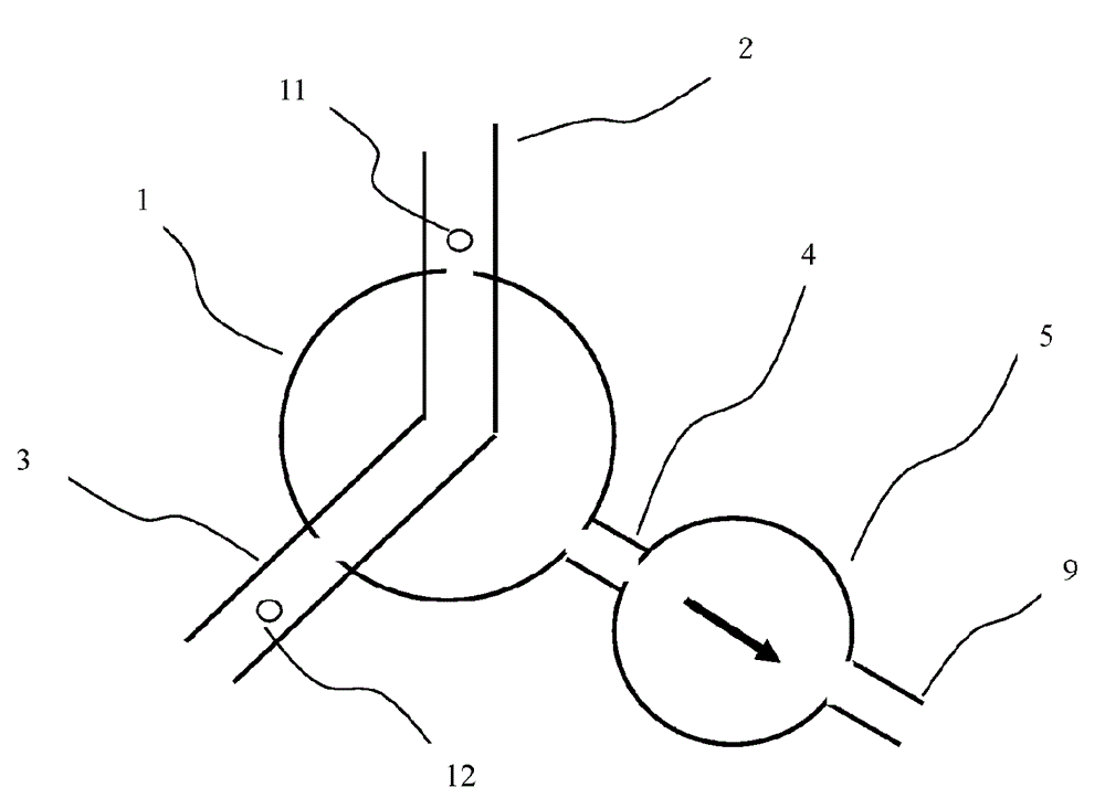
[0082] Embodiment 2: An electric three-way valve or an electric reversing valve is used to control the high temperature (or low temperature) liquid recycling device.
[0083] see figure 2 , Its working principle is the same as that of embodiment 1, except that the three-way structure 1 is an electric three-way valve or an electric reversing valve, which replaces the three-way pipe equipped with electric two-way valves 6, 7, and 8 of embodiment 1. Through the rotation of the electric three-way valve or the electric reversing valve, two of the inlet pipe 2, the outlet pipe 3, and the withdrawal pipe 4 are connected, and the other pipe is closed. Install a temperature sensor and a pressure sensor for sensing whether the liquid is flowing at position 11, install a pressure sensor for sensing whether the liquid is flowing and a conductivity sensor for sensing whether the liquid has been evacuated at position 12, when any pressure sensor measures When the liquid is flowing, the recycling device can be in working state, and the electric signal measured by the temperature sensor and/or the conductivity sensor that senses whether the liquid has been evacuated is used to control the rotation of the electric valve and the start and stop of the liquid pump. If the controller's circuit is designed to use the signal that the temperature of the liquid in the pipeline measured by the temperature sensor does not meet the requirements and the signal that the pressure sensor measures the beginning of the flow of the liquid to trigger the recycling device for recovery, the pressure sensor only One needs to be installed at position 11 or 12.

Example Embodiment

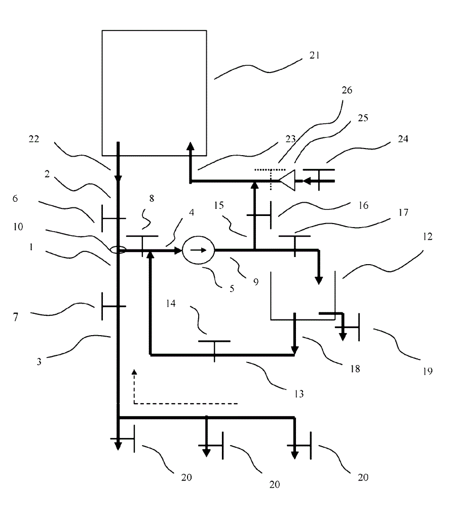
[0084] Example 3: Automatic recovery of low CO 2 Recycling device for water content.
[0085] see figure 1 , The recycling device is usually installed in high CO 2 At the outlet of the water content supply system, the inlet pipe 2 of the recycling device and the high CO 2 High CO in water supply system 2 The water outlet of the content water is connected, the outlet pipe 3 is connected with the pipeline on the user side, and the extraction pipe 4 is connected to the liquid pump 5 and the outlet pipe 9. The three-way structure 1 is respectively provided with a normally open inlet solenoid valve 6 and an outlet solenoid valve 7 And the normally closed solenoid valve 8 for the extraction pipe, the flow direction of the liquid is controlled by opening and closing the solenoid valve. Install a CO at position 10 in the three-way pipe between the solenoid valves 6, 7, and 8 of the three-way structure 1. 2 Saturation sensor (or pH sensor), a water ripple switch and a conductivity sensor (not shown in the figure). The sensor, water ripple switch and the liquid pump 5 are connected to the controller 30 in a wired manner. The controller 30 is The set control conditions and the signal of the sensor element control the opening and closing of the solenoid valve and the liquid pump. The water ripple switch is located in the power circuit of the recycling device. When the water ripple switch detects that the liquid in the pipeline starts to flow The recycling device enters the working state through the controller 30, CO 2 The saturation sensor (or pH sensor) and the conductivity sensor are based on the CO 2 Whether the saturation (or pH value) meets the requirements and whether the water has been evacuated to control the action of the solenoid valve and the liquid pump.
[0086] The specific working procedure is: turn on high CO 2 For the content water supply system, turn on the power switch of the recycling device and open the valve on the user side, the water in the pipeline starts to flow, and the water ripple switch makes the recycling device enter the working state; if CO 2 The saturation sensor measures the CO in the water in the pipeline 2 When the content does not meet the requirements, the signal of the sensor will open the outlet solenoid valve 7 and the outlet solenoid valve 8 through the controller, the liquid pump 5 will start, and the inlet solenoid valve 6 will be closed to recycle the low CO in the pipeline from the device to the user. 2 The content water is pumped out through the outlet pipe 3, the outlet solenoid valve 7, the three-way pipe, the outlet pipe solenoid valve 8, the outlet pipe 4, the liquid pump 5, and the outlet pipe 9 for reuse; when the conductivity sensor detects that there is no liquid in the pipeline At this time (the conductance is very small), the inlet solenoid valve 6 and the outlet solenoid valve 8 are opened by the controller, the liquid pump 5 continues to work, the outlet solenoid valve 7 is closed, and the recycling device is set to high CO 2 Content water supply system including high CO 2 Low CO remaining in the pipes inside the water supply system 2 The content water is pumped out through the inlet pipe 2, the inlet solenoid valve 6, the three-way pipe, the outlet pipe solenoid valve 8, the outlet pipe 4, the liquid pump 5, and the outlet pipe 9 for reuse (or rely on high CO 2 The pressure in the internal pipes of the water supply system maintains the movement of water and makes low CO 2 Content water flows out, do not start the liquid pump), at this time high CO 2 The content water supply system continuously adds CO to the water entering from the equipment inlet 2 , Make it reach the required CO 2 Saturation; when CO 2 Saturation sensor measured from high CO 2 CO in water from the water supply system 2 When the content has met the requirements, the solenoid valves 6 and 7 are restored to the open state through the controller, the solenoid valve 8 of the extraction pipe is restored to the closed state, and the liquid pump 5 stops working, meeting the required high CO 2 The content of water can be sent to the user end through the inlet pipe 2, inlet solenoid valve 6, three-way pipe, outlet pipe 3 and outlet solenoid valve 7 of the recycling device, and the released water is high CO 2 Content water.
[0087] Low CO extracted 2 Water content liquid can be used for washing items or other purposes, or directly pressed into high CO 2 CO is added to the liquid storage tank of the content water supply system 2 Use it again later.
[0088] For no high CO 2 For the supply system of the content water storage tank, the recycling device can also be installed in the water inlet pipeline of the supply system, that is, the inlet pipe 2 of the recycling device and the high CO 2 The inlet pipe of the content water supply system is connected, and the outlet pipe 3 is connected to the high CO 2 Water inlet connection of content water supply system, high CO 2 The outlet of the water content is connected to the pipeline on the user side, but its CO 2 The saturation sensor is not installed at position 10, but at high CO 2 At the liquid outlet of the content water supply system, and the outlet solenoid valve 7 can be omitted. The specific working procedure is: when the high CO 2 In the content water supply system, turn on the power switch of the recycling device and the valve on the user side, the water in the pipeline starts to flow, and the water ripple switch makes the recycling device work. If CO 2 The saturation sensor measures the CO of the water in the pipe at the outlet of the supply system 2 When the content does not meet the requirements of use, the sensor signal through the controller causes the extraction pipe solenoid valve 8 to open, the liquid pump 5 starts, and the inlet pipe solenoid valve 6 closes, which will recycle the device to the user end including the low CO in the pipeline inside the supply system 2 The content water is drawn through the outlet pipe 3, the three-way pipe, the outlet pipe solenoid valve 8, the outlet pipe 4, the liquid pump 5, and the outlet pipe 9 for reuse; when the conductivity sensor detects that there is no liquid in the pipeline (the conductivity is very high at this time) Small), the solenoid valve 6 is restored to the open state through the controller, the extraction pipe solenoid valve 8 is restored to the closed state, the liquid pump 5 stops working, and the raw water can pass from the inlet pipe of the supply system through the inlet pipe 2 of the recycling device. Valve 6, three-way pipe, outlet pipe 3 and high CO 2 Content water supply system adds CO 2 After it is sent to the user, the released water is high CO 2 Content water. If the water ripple switch detects that the liquid stops flowing during operation (such as closing the user-side valve or high CO 2 The water inlet or outlet valve of the content water supply system can make the device exit the working state, and can make the device re-enter the working state when the measured liquid starts to flow.

PUM

no PUM

Description & Claims & Application Information

We can also present the details of the Description, Claims and Application information to help users get a comprehensive understanding of the technical details of the patent, such as background art, summary of invention, brief description of drawings, description of embodiments, and other original content. On the other hand, users can also determine the specific scope of protection of the technology through the list of claims; as well as understand the changes in the life cycle of the technology with the presentation of the patent timeline. Login to view more.
Why Eureka
Try Eureka