Method of manufacturing optical film, optical film, deflection plate, and liquid crystal display device

A technology of optical film and convex part, applied in the direction of optics, optical elements, polarizing elements, etc., can solve the problems of yield reduction, blocking, film surface adhesion, etc.

Active Publication Date: 2012-05-30
KONICA MINOLTA OPTO
View PDF23 Cites 13 Cited by
  • Summary
  • Abstract
  • Description
  • Claims
  • Application Information

AI Technical Summary

Problems solved by technology

In addition, the hemming of the rolls also tends to cause close contact between the film surfaces (hereinafter referred to as clogging).
Wrinkles, scratches, etc. occur in the optical film protruding from the roll with black streaks or clogging, which makes it unsuitable for display devices, resulting in a decrease in yield

Method used


Image

  • Method of manufacturing optical film, optical film, deflection plate, and liquid crystal display device
  • Method of manufacturing optical film, optical film, deflection plate, and liquid crystal display device
  • Method of manufacturing optical film, optical film, deflection plate, and liquid crystal display device

Examples


Embodiment 1~17、 comparative example 1~8

[0246] According to the method for producing an optical film by the solution casting film forming method of the present invention, a cellulose triacetate film is produced as follows.

[0247] (mucil composition 1)

[0248]

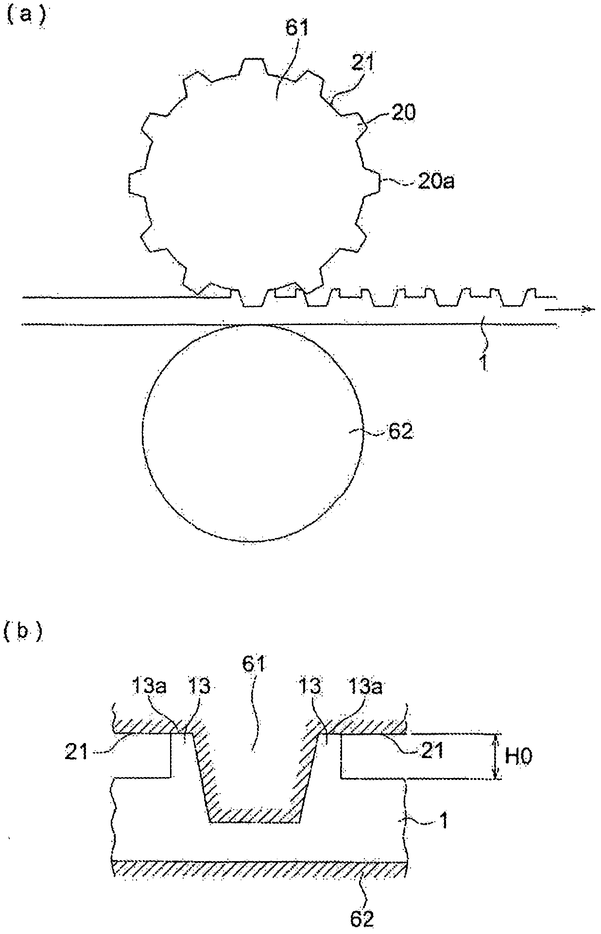
[0249] Put the material of the above-mentioned dope composition 1 into an airtight container, dissolve it completely while heating and stirring, and filter. Filtration After filtering with a filter press, it was passed through a metal sintered filter (captured particle diameter=10 micrometers). Next, use Figure 6 In the solution casting film-making device shown, at a temperature of 35°C, the dope is uniformly cast on a stainless steel belt support body with a width of 1800mm at a temperature of 35°C. Moreover, the molecular weight distribution of the cellulose triacetate differed, and the thing which showed two kinds of glass transition temperature Tg (degreeC) shown in Table 1 was used.

[0250] On the stainless steel belt support, the solvent was ...


PUM

PropertyMeasurementUnit
Average widthaaaaaaaaaa

Abstract

Disclosed is a method of manufacturing an optical film wherein a failure due to foreign matters, a black band while the film is rolled, and blocking never occur in the surface of the film, eliminating wrinkles and flaws. The method of manufacturing the optical film comprises a process of clamping a member comprising a plurality of projections onto both side edge sections of the long film in the width direction, thereby knurling the side edge sections by irregularity, and a process of taking up the film. In the process of knurling, the height of projecting portions formed by a film member clamped away by the projections when the projections are clamped onto the surface of the film is restricted by a flat portion configuring the base of the projections, so that the height of the projecting portions is determined height.

Description

technical field [0001] The present invention relates to a manufacturing method of an optical film, an optical film, a polarizer and a liquid crystal display device. Background technique [0002] In recent years, in addition to CRTs, various display devices such as liquid crystal televisions, plasma displays (PDPs), and organic EL displays have been developed, and their screen sizes are increasing. Along with the increase in screen size and high image quality, the area of ​​optical films used in display devices is also increasing, and the requirements for film uniformity are also increasing. As such an optical film, the polarizer protective film etc. which are used for the polarizer of a liquid crystal display device for protecting a polarizer are mentioned, for example. [0003] As an optical film for such a display device, in particular, a wide film having a width of 1000 mm or more, further 1400 mm or more is required due to the recent enlargement of the screen. In addit...

Claims


Application Information

Patent Timeline
IPC IPC(8): G02B5/30B29D11/00G02F1/1335
CPCB29D11/0074B29C59/04
Inventor 前田贤一
Owner KONICA MINOLTA OPTO
Why Eureka
Try Eureka