Detection bench, detection method and detection system

A detection system and detection method technology, applied in the direction of lamp testing, testing optical performance, etc., can solve the problem of shortening the production line of light-emitting components, and achieve the effect of reducing the overall volume and quantity, and reducing the volume and length.

Inactive Publication Date: 2012-06-06
LEXTAR ELECTRONICS CORP
View PDF5 Cites 28 Cited by
  • Summary
  • Abstract
  • Description
  • Claims
  • Application Information

AI Technical Summary

Problems solved by technology

[0007] Based on the above, it can be seen that if you want to perform high temperature detection and low temperature detection of light-emitting elements, you need t

Method used


Image

  • Detection bench, detection method and detection system
  • Detection bench, detection method and detection system
  • Detection bench, detection method and detection system

Examples


Embodiment Construction

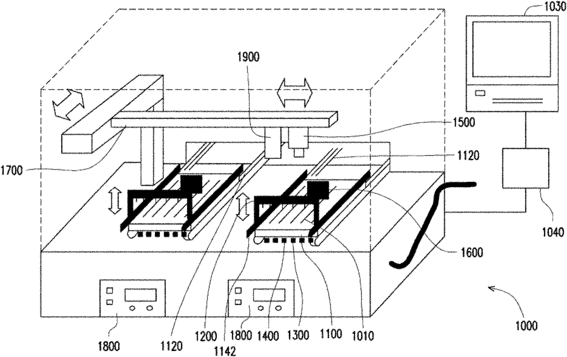
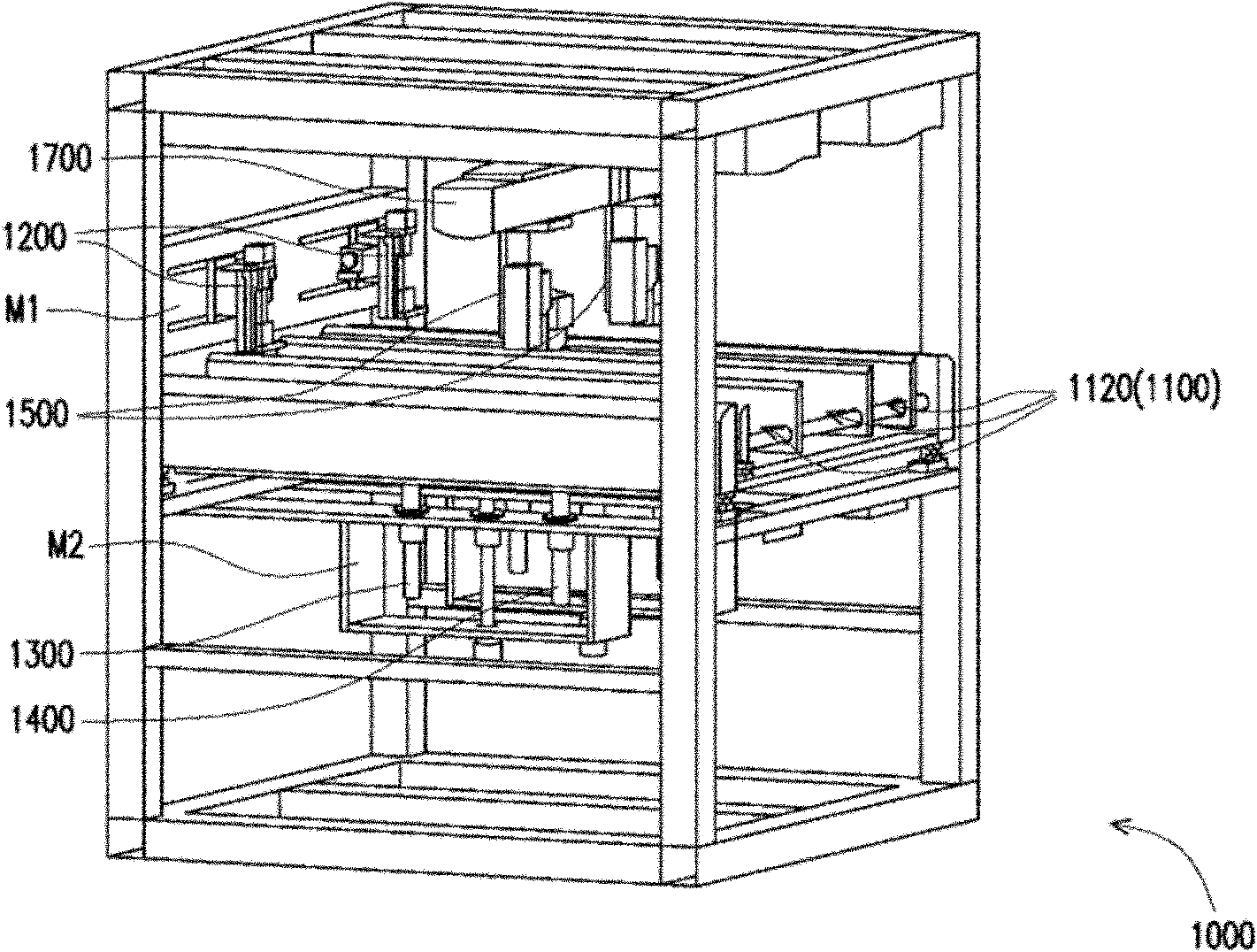
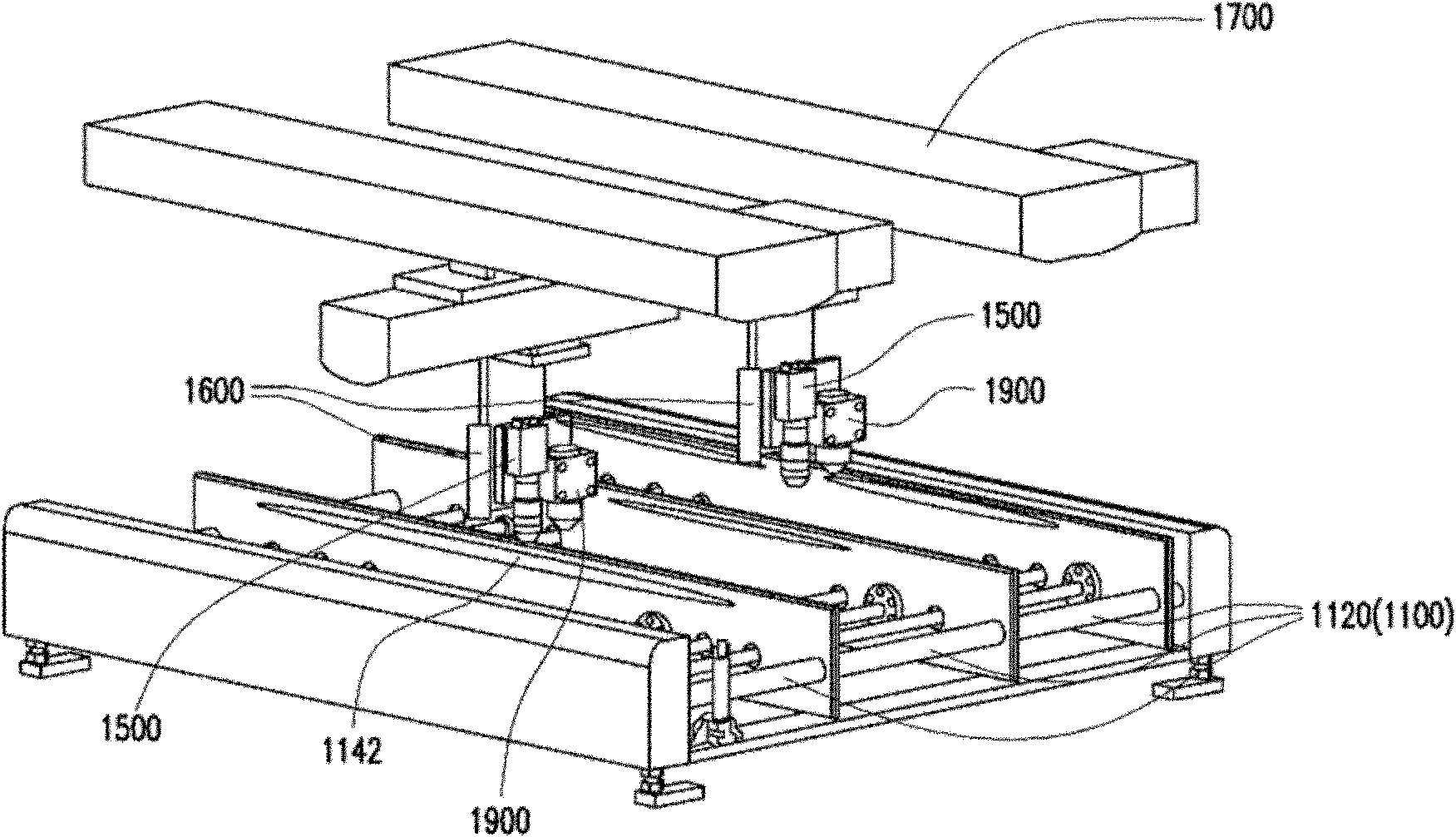
[0062] figure 1 It is a simple schematic diagram of a testing machine according to an embodiment of the present invention, figure 2 then figure 1 The partial three-dimensional schematic diagram of the specific implementation of the detection machine, and image 3 then figure 2 A partial enlarged schematic diagram of the testing machine. Please also refer to figure 1 , figure 2 and image 3 , the detection machine 1000 of this embodiment is suitable for performing optical and electrical detection on a light-emitting element 1010 . Specifically, the testing machine 1000 includes a substrate platform 1100 , a probe mechanism 1200 , a heating device 1300 , a cooling device 1400 , an image sensing device 1500 , a temperature sensing device 1600 and a moving platform 1700 . The light emitting element 1010 is disposed on the substrate platform 1100 . In this embodiment, the substrate platform 1100 is as follows figure 2 and image 3 The conveyor belt device 1120 is show...


PUM


Abstract

The invention discloses a detection bench, a detection method and a detection system. The detection bench can be used for the optical and electrical detection of the light-emitting component. The detection bench comprises a substrate platform, a probe mechanism, a heating device, a cooling device, an image sensing device, a temperature sensing device, and a movable platform. The probe mechanism is suitable for the contact with the light-emitting component, and is close to the substrate platform. The heating device is suitable for heating the light-emitting component to make the temperature of the light-emitting component to remain in the first temperature range. The cooling device can be used to cool the light-emitting component to make the temperature of the light-emitting component to remain in the second temperature range. The image sensing device can be used to sense the light-emitting image generated by the light-emitting component. The temperature sensing device can be used to sense the current temperature of the light-emitting component. The image sensing device is disposed on the movable platform, which is suitable for moving the image sensing device. The invention also provides a detection method and a detection system, which are suitable for the above mentioned detection bench.

Description

technical field [0001] The invention relates to a detection machine, a detection method and a detection system, and in particular to a low-cost and high pass rate detection machine, detection method and detection system. Background technique [0002] Traditionally, in order to perform various optical inspections and electrical inspections on light-emitting elements (such as LED strips), various optical inspection and electrical inspection machines are usually set up, and the light-emitting elements are sent to these inspections in sequence. In the machine, the optical properties and electrical performance of light-emitting elements can be measured. Specifically, the light-emitting element is judged as one station by the residual temperature visual inspection after the reflow oven, and the power supply and the probe mechanism are manually adjusted to light up, and then the visual inspection is used to check whether the LED is on and the appearance inspection, such a high-temp...

Claims


Application Information

Patent Timeline
IPC IPC(8): G01R31/44G01M11/02
Inventor 谢孝樑林文迪谢祥政
Owner LEXTAR ELECTRONICS CORP
Why Eureka
Try Eureka