Mulser

An emulsifying machine and emulsifying tank technology, applied in the field of emulsifying machines, can solve the problems of poor emulsifying effect, long stirring and cutting time, low water content, etc., and achieve the effects of high emulsifying efficiency, small volume and low energy consumption

Inactive Publication Date: 2012-06-13
JIANGSU HUANNENGTONG ENVIRONMENTAL PROTECTION TECH
View PDF3 Cites 11 Cited by
  • Summary
  • Abstract
  • Description
  • Claims
  • Application Information

AI Technical Summary

Problems solved by technology

The commonly used emulsifier has a structure similar to that of a mixer, with a stirring shaft and blades installed on the stirring shaft, but it also has the defects of a common mixer, that is, a long mixing time, poor emulsification effect, low water content and excessive energy consumption.

Method used


Image

  • Mulser
  • Mulser

Examples


Embodiment Construction

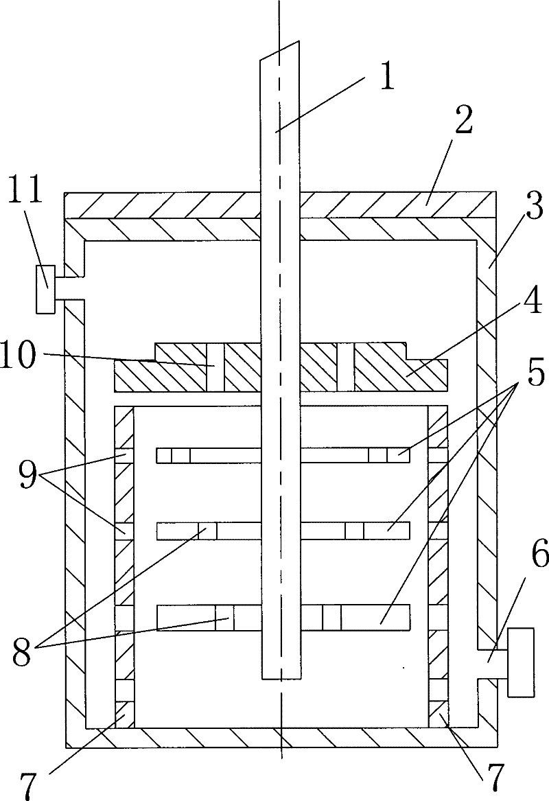
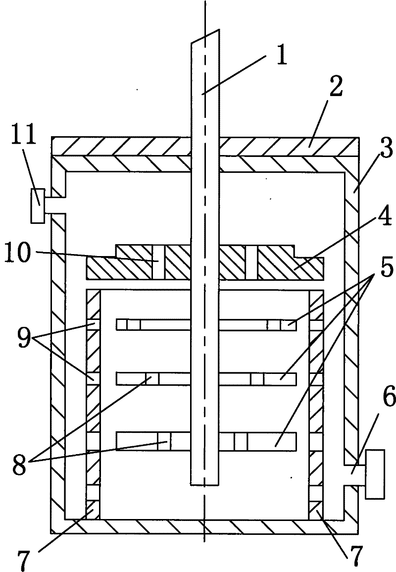
[0010] Such as figure 1 As shown, the top of the emulsification tank 3 is the tank cover 2, and the stirring shaft 1 extends vertically into the emulsification tank 3 from the outside of the top of the emulsification tank 3 through the tank cover 2. The upper part of one side of the emulsification tank 3 is provided with a feed port 11, and the lower part is provided with a discharge port 6. The impeller 4 is fixedly arranged on the stirring shaft 1 in the emulsification tank 3 , and the impeller 4 is arranged horizontally, perpendicular to the stirring shaft 1 , and several third holes 10 are opened on the impeller 4 .

[0011] Just below the impeller 4 is provided with a dispersing tube 9 whose upper port communicates with the lower port. The dispersing tube 9 is coaxial with the stirring shaft 1. The dispersing tube 9 is vertically fixed on the bottom of the emulsification tank 3. The top of the dispersing tube 9 is close to the impeller 4 and There is a gap with the impel...


PUM


Abstract

The invention discloses a mulser. A stirring shaft vertically extends into an emulsification can from the outside of the top portion of the emulsification can through a can cover, an impeller is fixedly arranged on the stirring shaft in the emulsification can, and the impeller is horizontally arranged and provided with a plurality of third holes. A dispersing barrel with an upper opening communicated with a lower opening and coaxial with the stirring shaft are arranged right below the impeller, the dispersing barrel is perpendicularly and fixedly connected with the bottom of the emulsification can, the top portion of the dispersing barrel is close to the impeller, and a gap is reserved between the top portion of the dispersing barrel and the impeller. A gap is reserved between the outer wall of the dispersing barrel and the inner wall of the emulsification can. The lateral wall of the dispersing barrel is provided with a plurality of second holes, multi-layer blades horizontally arranged and fixedly connected with the stirring shaft are arranged in the dispersing barrel at intervals along the axial direction of the stirring shaft. Each layer of blades is composed of a plurality of straight rods evenly distributed along the circumferential direction of the stirring shaft, and a plurality of first holes are arranged on each straight rod. The mulser is applied to continuous dispersing and emulsification for materials with high viscosity and can finely and evenly crush emulsification medium particles.

Description

technical field [0001] The invention relates to the field of production equipment for lithium-ion battery slurry, in particular to an emulsifying machine for emulsifying lithium-ion battery slurry. Background technique [0002] As a new generation of environmentally friendly and high-energy batteries, lithium-ion batteries are widely used in portable appliances such as laptops, cameras, mobile communications and electric vehicles, and have become one of the key points in the development of the battery industry. The main constituent materials of lithium-ion batteries include electrolyte, separator, positive and negative electrode materials, etc. Among them, the positive and negative electrode materials occupy the most important position. The positive and negative electrode materials directly determine the performance of the final lithium-ion battery product, and high-quality positive and negative electrodes The formation of the negative electrode material is determined by an ...

Claims


Application Information

Patent Timeline
Patent Type & Authority Applications(China)
IPC IPC(8): B01F7/18B01F7/26B01F15/00B01F3/08B01F3/10B01F23/47B01F27/93
Inventor 王辉
Owner JIANGSU HUANNENGTONG ENVIRONMENTAL PROTECTION TECH
Why Eureka
Try Eureka