Air-floated high-speed motorized spindle

A technology of high-speed electric spindle and air bearing, which is applied in the direction of clamping, supporting, positioning devices, etc., can solve the problems that the working speed of the rotor cannot be changed, affects the service life of the electric spindle, and the rotor is easily damaged, so as to achieve friction reduction, Eliminates mechanical friction and achieves high rotational speed

Inactive Publication Date: 2012-06-13
GUANGZHOU HAOZHI ELECTROMECHANICAL
View PDF2 Cites 24 Cited by
  • Summary
  • Abstract
  • Description
  • Claims
  • Application Information

AI Technical Summary

Problems solved by technology

The stator uses a non-variable frequency power supply, so the working speed of the rotor cannot be changed, and the function

Method used


Image

  • Air-floated high-speed motorized spindle
  • Air-floated high-speed motorized spindle
  • Air-floated high-speed motorized spindle

Examples


Embodiment 1

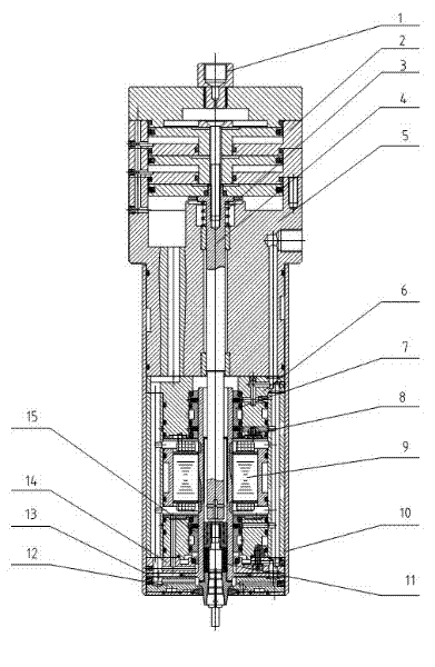
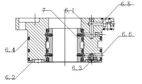
[0032] according to Figure 1 to Figure 6 As shown in the figures, in the present invention, in the existing tool change cylinder assembly 2 with pipe joint 1, the bottom of the tool change cylinder assembly 2 is fixed with the top end of the aluminum water jacket assembly 5 with power cord, air source hole and cooling water source , The bottom end of the aluminum water jacket assembly 5 fixes the top end of the organic body assembly 10, the top, middle and bottom of the axial through hole of the body assembly 10 are respectively fixed with the upper air bearing seat assembly 6, the stator 9 with temperature sensor and the lower air Based on the floating bearing seat assembly 14, the present invention is particularly in that the upper air bearing seat assembly 6 and the lower air bearing seat assembly 14 are respectively fixed with an upper air bearing 7 and a lower air bearing 15 in the axial through holes, There is an axial core 8 passing through an axial through hole between...

Embodiment 2

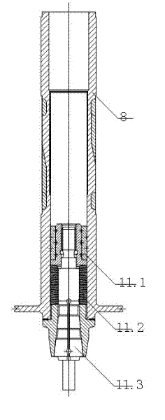
[0034] It is the same as Embodiment 1, except that the top and the bottom of the chuck attachment 11 are respectively composed of a shaft main body 11.1, a butterfly spring 11.2 and a chuck 11.3.

Embodiment 3

[0036] Same as embodiment 1, except that the aluminum water jacket assembly 5 includes a connecting seat as an aluminum water jacket. The upper port of the connecting seat and the outer wall near the bearing seat are both provided with a sealing ring 5.3, and the middle of the connecting seat is provided There is an axially penetrating push rod hole. The outer wall of the connecting seat between the two sealing rings 5.3 is provided with a cooling water groove. One side wall of the connecting seat is provided with a water inlet hole that communicates with the cooling water groove. The opening is provided with a plug 5.2; the inner wall of the push rod hole is provided with at least one sliding sleeve 5.1; the air inlet and the water return hole are respectively arranged on the side wall of the connecting seat, and both are connected to the bottom end surface of the connecting seat ; On the opposite side wall of the bearing seat is provided with a return hole and a power connecto...


PUM


Abstract

The invention relates to an air-floated high-speed motorized spindle, particularly to a mechatronic basic part with high rotating speed and high precision. The air-floated high-speed motorized spindle disclosed by the invention is characterized in that an upper air-floated bearing (7) and a lower air-floated bearing (15) are respectively fixed in axial through holes of an upper air-floated bearing pedestal assembly (6) and a lower air-floated bearing pedestal assembly (14), and a central spindle (8) runs through an axial through hole among the upper air-floated bearing (7), a stator and the lower air-floated bearing (15); and a gap of 0.03-0.035 mm is formed between the outer wall of the central spindle (8) and the inner walls of the upper air-floated bearing (7) and the lower air-floated bearing (15). The air-floated high-speed motorized spindle disclosed by the invention has the advantages of simple and compact structure, convenience of installation, changeable rotating speed due to utilization of a variable-frequency power source, long service life and convenience for popularization and application.

Description

Technical field [0001] The invention relates to a mechanical processing equipment, in particular to a high-speed, high-precision mechatronics basic part. Background technique [0002] In the prior art, the aluminum water jacket assembly for the air-floating high-speed electric spindle has a complex structure, is not conducive to the heat dissipation of the spindle, is inconvenient to install, has a single function, and is difficult to grasp the assembly accuracy. The bearing seat assembly has a single structure, difficult processing, inconvenient loading and unloading, low heat dissipation capacity, and large vibration amplitude. The spindle chuck attachment is used to fix the tail of the chuck and increase the stability of the chuck. However, when the spindle rotates at a high speed, the distance between the shaft core and the bearing will cause friction, and if the distance is too large, the shaft core will be unstable during operation. The stator uses a non-frequency conv...

Claims


Application Information

Patent Timeline
IPC IPC(8): B23B19/02B23Q3/155B23Q11/12
CPCB23Q3/155B23Q2220/006B23Q1/70B23Q11/12B23Q5/10
Inventor 汤秀清
Owner GUANGZHOU HAOZHI ELECTROMECHANICAL
Why Eureka
Try Eureka