Alternating current detection circuit and automatic power-off circuit with zero power-off power consumption

A technology of alternating current and detection circuit, which is applied in the direction of measuring current/voltage, emergency protection device for automatic disconnection, circuit device, etc., and can solve problems such as complex structure, power consumption, and high production cost

Inactive Publication Date: 2012-06-13
HEFEI UNIV OF TECH
View PDF5 Cites 7 Cited by
  • Summary
  • Abstract
  • Description
  • Claims
  • Application Information

AI Technical Summary

Problems solved by technology

However, the electrical equipment in the standby state will consume electric energy, and the equipment will be in the standby state for a long time, which will cause a lot of waste of electric energy.
At work, after get off work, the staff often turn off the computer without unplugging or turning off the socket, so that the main computer equipment, monitors, printers and other auxiliary equipment are in a state of power on, and these equipment will still consume a certain amount of power. , resulting in a large waste of power resources
[0004] Existing energy-saving sockets with automatic power-off function, after the socket is cut off, the internal circuit of the socket itself is still in the energized state, which will also cause a waste of one unit of power resources, and the socket and electrical equipment cannot be powered off together, which will cause waste of power res

Method used


Image

  • Alternating current detection circuit and automatic power-off circuit with zero power-off power consumption
  • Alternating current detection circuit and automatic power-off circuit with zero power-off power consumption
  • Alternating current detection circuit and automatic power-off circuit with zero power-off power consumption

Examples


Embodiment Construction

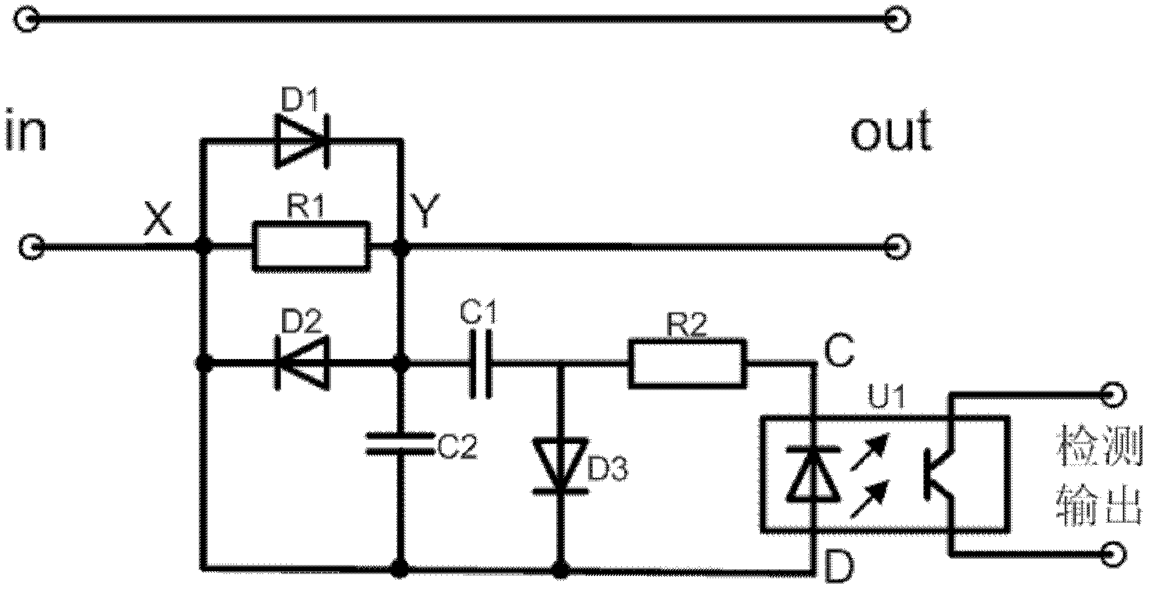
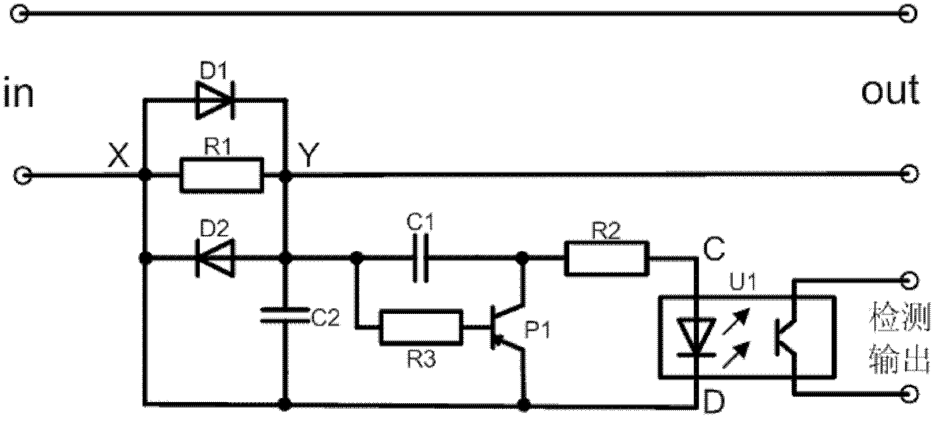
[0021] see Figure 1 to Figure 4 , an alternating current detection circuit, including a resistor R1, a resistor R2, a capacitor C1, a filter element C2, a diode D1, a diode D2, and a photoelectric tube U1; the positive end of the diode D1 is connected to the negative end of the diode D2, and the connecting end is an end point X; the negative end of the diode D1 and the positive end of the diode D2 are connected to each other, and the connecting end is the terminal Y; the two ends of the resistor R1 are respectively connected to the terminal X and the terminal Y; one end of the capacitor C1 is connected to the terminal Y. The terminal Y is connected, the other end of the capacitor C1 is connected to the connection terminal C of the photoelectric tube U1 through the resistor R2; one end of the filter element C2 is connected to the terminal Y, and the filter element C2 The other end of the photoelectric tube U1 is connected to the connecting terminal D; the terminal X is connect...


PUM


Abstract

The invention discloses an alternating current detection circuit and an automatic power-off circuit with zero power-off power consumption. The alternating current detection circuit comprises resistors R1 and R2, a capacitor C1, a filter element C2, diodes D1 and D2, and a photoelectric tube U1, wherein a positive end of the diode D1 is connected with a negative end of the diode D2, and a connecting end is an end point X; the negative end of the diode D1 is connected with the positive end of the diode D2, and the connecting end is an end point Y; two ends of the resistor R1 are connected with the end point X and the end point Y; and the alternating current detection circuit also comprises a diode D3 or a triode P1. The automatic power-off circuit with the zero power-off power consumption is provided with the alternating current detection circuit which serves as a current detection device. By adoption of the alternating current detection circuit and the automatic power-off circuit, a current can be quite conveniently detected, a circuit structure is easy to minimize, and after electric equipment is closed, a socket can be totally disconnected from an external power supply.

Description

technical field [0001] The invention relates to an alternating current detection circuit and an automatic power-off circuit with zero power consumption during power-off. Background technique [0002] Common methods of current detection include the following types: series resistance detection, current transformer detection and Hall device detection. Each of these types of tests has its own advantages and disadvantages. Resistance detection is only suitable for lines with small currents. In a high-current detection circuit, if the insertion loss is large if the resistance is connected in series, the power dissipation will be several watts or even tens of watts. , especially in the case of a large load current variation range, it is difficult to take care of the dual requirements of detection sensitivity and high current tolerance by the detection method of series resistance. In this case, this method is generally not used; in the detection of large currents, the common meth...

Claims


Application Information

Patent Timeline
IPC IPC(8): G01R19/00H02H3/00
Inventor 项学海项宾富窦本银史红叶
Owner HEFEI UNIV OF TECH
Why Eureka
Try Eureka