Novel permanent magnetism auxiliary exciter rotor structure

A permanent magnet auxiliary exciter and rotor structure technology, applied in the direction of magnetic circuit shape/style/structure, magnetic circuit rotating parts, etc., can solve the problems of poor workmanship, poor economy, large magnetic flux leakage coefficient, etc., and achieve the utilization of magnetic steel The effect of high efficiency, convenient processing, and small magnetic flux leakage coefficient

Inactive Publication Date: 2012-06-13
SEC ELECTRIC MACHINERY
View PDF3 Cites 5 Cited by
  • Summary
  • Abstract
  • Description
  • Claims
  • Application Information

AI Technical Summary

Problems solved by technology

[0011] Aiming at the shortcomings of the above two main structures, such as poor manufacturability, large flux leakage coefficient, and poor economy, the applicant provides a new type of permanent magnet auxiliary exciter rotor with convenient parts processing, convenient assembly operation, good performance, stability and reliability. structure to meet the characteristics of high stability requirements of the turbogenerator system

Method used


Image

  • Novel permanent magnetism auxiliary exciter rotor structure
  • Novel permanent magnetism auxiliary exciter rotor structure
  • Novel permanent magnetism auxiliary exciter rotor structure

Examples


Embodiment Construction

[0020] The specific implementation manner of the present invention will be described below in conjunction with the accompanying drawings.

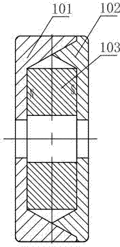
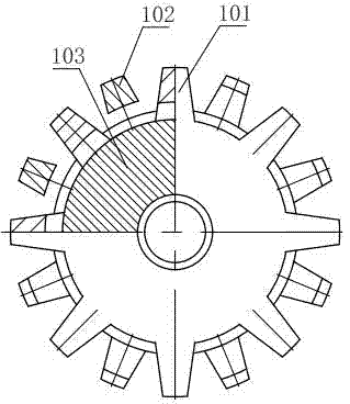
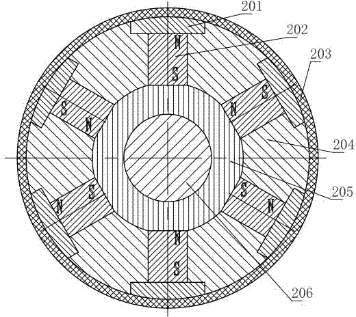
[0021] Such as Figure 4 As shown, the novel permanent magnet sub-exciter rotor structure of the present invention is provided with a rotating shaft 5 inside the annular yoke 4, and the permanent magnet 2 and the pole piece 1 are locked on the outer periphery of the annular yoke 4 by stainless steel screws 3 on the yoke. 4, the number of stainless steel screws 3 is determined according to the calculation of mechanical strength.

[0022] The invention adopts stainless steel screws to directly rake the pole shoe and the permanent magnet on the yoke. The parts are easy to process, easy to assemble and operate, and the air gap is small, the magnetic flux leakage coefficient is small, the utilization rate of the magnetic steel is high, the performance is good, stable and reliable.


PUM


Abstract

The invention discloses a novel permanent magnetism auxiliary exciter rotor structure. An annular magnet yoke is internally provided with a rotating shaft, and a permanent magnet and a pole shoe are locked on the magnet yoke tightly at peripheral of the annular magnet yoke through a stainless steel screw. According to the invention, the stainless steel screw is employed to directly fix the pole shoe and the permanent magnet on the magnet yoke together, compared with a present rotor structure of a bound permanent magnetism auxiliary exciter, weftless glass riband and nonmagnetic filling materials are cancelled, not only are component processing and assembling operation convenient, but also air gap is small, a magnetic leakage coefficient is small, magnetic steel utilization rate is high, and performance is good, stable and reliable.

Description

technical field [0001] The invention relates to the field of permanent magnet generators, in particular to a rotor structure of a permanent magnet auxiliary exciter used in a brushless excitation system of a steam turbine generator. Background technique [0002] Before the 1990s, turbogenerators of 100MW and above used four-pole small hidden pole laminated rotor synchronous generators as the exciter, and the auxiliary exciter was used as the power supply for the main exciter. In the early days, the induction sub-motor was used as the auxiliary exciter. When the motor starts, it needs an external excitation power supply. When the unit is running, the controllable self-excited constant voltage device maintains constant voltage operation. Due to the controllable rectification load of the induction sub-exciter, and the influence of the rotor convex teeth and the horizontal axis armature reaction, the voltage waveform is greatly distorted; The existence of the self-excited const...

Claims


Application Information

Patent Timeline
Patent Type & Authority Applications(China)
IPC IPC(8): H02K1/28
Inventor 邓广才
Owner SEC ELECTRIC MACHINERY
Why Eureka
Try Eureka