Non-contact dynamic detection device and detection method for tire tread defects

A dynamic detection, non-contact technology, applied in the direction of wheel rim measurement/measurement, optical test defect/defect, etc., can solve the problems of human measurement error and low measurement efficiency, reduce human error, improve use efficiency, and avoid wear and tear Effect

Inactive Publication Date: 2012-06-20
ZHENGZHOU UNIVERSITY OF LIGHT INDUSTRY
View PDF4 Cites 17 Cited by
  • Summary
  • Abstract
  • Description
  • Claims
  • Application Information

AI Technical Summary

Problems solved by technology

[0005] The technical problem to be solved by the present invention is that at present, wheel tread defects need to be stopped for detection, there are artificial measurement errors, and the measurement efficiency i

Method used


Image

  • Non-contact dynamic detection device and detection method for tire tread defects
  • Non-contact dynamic detection device and detection method for tire tread defects
  • Non-contact dynamic detection device and detection method for tire tread defects

Examples


Embodiment 1

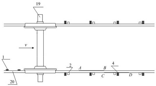
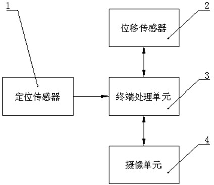
[0035] Embodiment 1: as figure 1 and figure 2 As shown, the present invention includes a terminal processing unit 3, and also includes a positioning sensor 1 arranged on one side of the rail. 4 connected. When the train is running, the rails are arranged in pairs, and the positioning sensor 1 is arranged on one side of the rail. 2 and camera unit 4 mean that the outer surfaces of the two rails 20 are provided with displacement sensors 2 and camera units 4 , and for any one of the rails, the displacement sensor 2 and camera unit 4 are located on one side of the rail 20 .

[0036] The positioning sensor 1 is two eddy current sensors or two photoelectric switches, and the displacement sensor 2 is a laser displacement sensor. The speed of the train is detected by the positioning sensor 1, the position of the tread defect on the tread circumference is judged by the displacement sensor 2 according to the scattered light signal of the wheel tread, the image of the defect is captu...

Embodiment 2

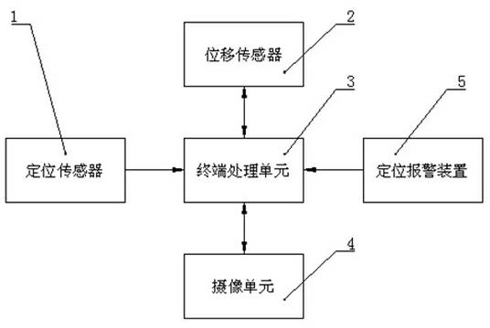
[0047] Embodiment 2: as image 3 As shown, the output end of the terminal processing unit is connected with a positioning alarm device, and other structures are the same as those in Embodiment 1.

[0048] The detection steps in this embodiment are as follows: Steps A, B, C, and D are the same as those in Embodiment 1. Afterwards, the terminal processing unit compares the calculated defect size with the set defect value. When the calculated defect is greater than the set defect value, The terminal processing unit sends a signal to the positioning alarm device, and the positioning alarm device records the defective wheels and sends out an alarm signal.

[0049] The positioning alarm device can record which wheel the defective wheel is on the carriage, so that the staff can quickly designate the maintenance point.


PUM


Abstract

The invention discloses a non-contact dynamic detection device and a detection method for tire tread defects, wherein, the non-contact dynamic detection device comprises a terminal processing unit and a positioning sensor; the positioning sensor is arranged on one side of a steel rail; the positioning sensor is connected with the terminal processing unit; and the terminal processing unit is connected with a displacement sensor and a camera unit which are arranged on both sides of the steel rail. The invention has the outstanding advantages as follows: firstly, a non-contact dynamic measuring method is adopted, and on-line dynamic detection can be achieved; secondly, the circumference of a tire tread can be detected roundly; thirdly, the type of the tire tread defects can be distinguished according to texture characteristics, and corresponding defect parameters can be calculated according to the type, wherein, the type of the tire tread defects is divided into scraping and stripping; and fourthly, small personal error can be caused.

Description

technical field [0001] The invention relates to a wheel flaw detection device, in particular to a non-contact wheel tread detection device. Background technique [0002] With the development of my country's railway industry, the speed of trains continues to increase, and people pay more and more attention to the safety of vehicle operation. At the same time, the requirements for automation of train maintenance and repair are also getting higher and higher. For the normal and safe operation of trains, it is necessary to improve maintenance efficiency and quality. In the railway application, the running state of the out-of-shape parts, especially the wheelset, plays an important role in the safety of the train. The tread defects of the wheel set will bring additional impact and vibration to the train during operation, which will affect the safety and service life of the train and track facilities. Vehicle wheel set tread defects include tread galling and tread peeling. Tread...

Claims


Application Information

Patent Timeline
IPC IPC(8): B61K9/12G01N21/88
Inventor 张志峰杨坤任宇芬薛人中朱祥李俊丰
Owner ZHENGZHOU UNIVERSITY OF LIGHT INDUSTRY
Why Eureka
Try Eureka