Multi-disc type fine-pitch magnetorheological clutch

A magneto-rheological and clutch technology, applied in the direction of fluid clutches, clutches, mechanical equipment, etc., can solve the problems of small transmission torque, small structure volume, large transmission torque, etc., and achieve large transmission torque, high safety and reliability, and high transmission torque change effect

Inactive Publication Date: 2012-06-20
CHINA UNIV OF MINING & TECH
View PDF7 Cites 29 Cited by
  • Summary
  • Abstract
  • Description
  • Claims
  • Application Information

AI Technical Summary

Problems solved by technology

Foreign patents: U.S. Patent 5896965 discloses a magneto-rheological sector clutch, which adopts a single-disc structure and can realize intelligent control of torque transmission, but its transmission torque is small; U.S. Patent 5823309 discloses a multi-disc magnetic flow clutch. Variable transmission device, which can realize the transmission of large torque, but its heat generation is large, there is no cooling device, and the slip power is small; domestic patent: CN101915277A introduces a single-plate three-disc magneto-rheological clutch, which combines discs There are two working modes of type and cylinder type, which have the advantages of small structure size and large transmission torque, but without cooling system, poor heat dissipation performance and narrow slip range; CN1523251A discloses a V-shaped magneto-rheological stepless transmission, which adopts Double V-shaped structure, simple structure, but only suitable for industrial low-power occasions; CN1648483A discloses a heat pipe magnetorheological soft start device, which adopts a new heat pipe heat dissipation method, has good heat dissipation performance, but is only suitable for transmission For small torque

Method used


Image

  • Multi-disc type fine-pitch magnetorheological clutch
  • Multi-disc type fine-pitch magnetorheological clutch
  • Multi-disc type fine-pitch magnetorheological clutch

Examples


Embodiment Construction

[0015] The present invention and an embodiment are further described below in conjunction with accompanying drawing:

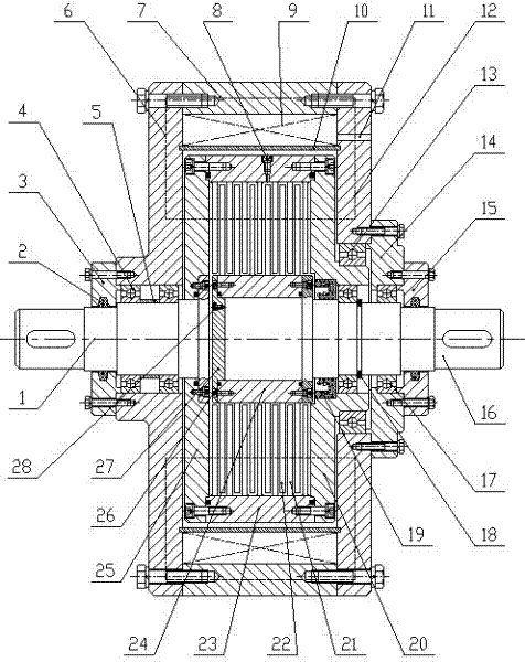
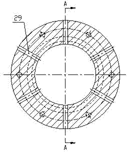
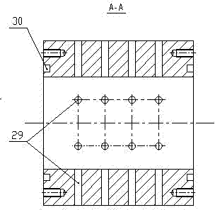
[0016] The multi-disk micro-pitch magneto-rheological clutch of the present invention is mainly composed of an input end part, an output end part, a magnetically conductive shell, and a supporting and sealing device. Wherein: the input end part comprises driving shaft 1, left and right baffle plates 25, 20, magnetic isolation sleeve 23 and driving disk 21, and driving disk 21 is installed in the magnetic isolation sleeve 23 by welding mode clearance, the radial setting of driving disk 21 There are multiple radial liquid return ports 31, and the number of radial liquid return ports 31 is 4 to 8, evenly distributed. During operation, the magnetorheological fluid can flow repeatedly between the main and driven discs 21 and 22, so as to accelerate the heat dissipation of the magnetorheological fluid and improve the stability of the magnetorheological fluid....


PUM


Abstract

A multi-disc type fine-pitch magnetorheological clutch mainly consists of a driving shaft, a driven shaft, a magnetic conduction shell, magnetic conduction baffle plates, a magnet exciting coil, driving discs, driven discs, a magnetic isolated sleeve, a magnetic isolated hub, a support and a sealing device. The driving discs and the driven discs are respectively mounted on the magnetic isolated sleeve and the magnetic isolated hub in a clearance manner, and are respectively connected with the driving shaft and the driven shaft via the magnetic conduction baffle plates, a clearance between each driving disc and the adjacent driven disc is micron-sized, magnetorheogical fluid is fully filled in the clearances, the magnet exciting coil is fixed in a cavity formed by the magnetic conduction shell and a magnetic isolated copper ring, cooling liquid is filled in a cavity of the magnetic isolated hub via a water injection screw plug, sealing of the cooling liquid is realized by a sealing ring, during working, the cooling liquid flows into the driven discs via radial round holes on the magnetic isolated hub, heat dissipation of working devices is accelerated, the temperature of the magnetorheogical fluid is reduced, and slip frequency power of the device is increased. The multi-disc type fine-pitch magnetorheological clutch is compact in structure, high in transmission torque, fine in heat dissipation performance and long in service life, and does not generate electric sparks.

Description

technical field [0001] The invention relates to a magneto-rheological clutch, in particular to a multi-disc micro-pitch magneto-rheological clutch used for the transmission of high-power mechanical equipment. Background technique [0002] A clutch is a device used to transmit power or motion in a mechanical system, which can realize the engagement and separation of the main and driven parts. At present, traditional clutches include jaw clutches, friction clutches, and fluid couplings. The jaw clutch has a simple structure, and there is no relative movement between the two shafts. It is generally suitable for low-speed joints and occasions where the transmission torque is not large; the friction clutch can realize the joint or separation of the two shafts at any speed. The joint process is stable and the impact vibration is relatively small. It is small and has the function of overload protection, but its size is large, the heat generation is large, and the wear of the frict...

Claims


Application Information

Patent Timeline
IPC IPC(8): F16D37/02
Inventor 王道明侯友夫
Owner CHINA UNIV OF MINING & TECH
Why Eureka
Try Eureka