High-adaptability composite material pipe joint

A composite material pipe and composite material technology, applied in the field of composite material pipe joints, can solve the problems of difficult manufacturing, complicated process, and inability to adapt to complex and changeable joint forms.

Inactive Publication Date: 2012-06-20
NANJING INST OF ASTRONOMICAL OPTICS & TECH NAT ASTRONOMICAL OBSE
View PDF7 Cites 8 Cited by
  • Summary
  • Abstract
  • Description
  • Claims
  • Application Information

AI Technical Summary

Problems solved by technology

The design of the above-mentioned composite material pipe joint has complex process, difficult processing and manufacturing, and insufficient flexibility, especially in the occasions where the joint form is complex and changeable.

Method used


Image

  • High-adaptability composite material pipe joint
  • High-adaptability composite material pipe joint
  • High-adaptability composite material pipe joint

Examples


Embodiment 1

[0046] In the figure: 1. Schematic ball joint nodes, 2. Metal connectors, 3. Metal tightening taper sleeves, 4. Composite pipe fittings.

[0047] exist Figure 7 In the shown embodiment, the inner wall of the end is turned, and the composite material pipe 4 and the metal tapered pipe 2 and the metal tightening taper sleeve 3 are connected and matched with an appropriate adhesive, and then the composite material pipe is smeared. 4 is inserted into the metal tightening cone pipe 3; the inner and outer pipe walls at the joint of the composite material pipe 4 and the middle of the sawn seam are coated with appropriate adhesive; the tapered part of the metal cone pipe 2 is inserted into the composite material pipe 4, and the metal connection The taper of the piece opens the nozzle of the composite material pipe until the end face of the nozzle is against the side of the middle section of the metal tapered pipe 2; then the adhesive in the composite material pipe 4 and its seam is sp...

Embodiment 2

[0049] exist Figure 8 In the shown embodiment, after the adhesive is applied on the inner and outer walls of the joint of the composite pipe 4 and the middle of the sawn seam, the metal connector 2 is connected to the metal tightening taper sleeve (metal tightening vertebral tube) 3 through matching threads. Together (but not completely tightened, leaving a small gap first), insert the composite material tube 4, and use the taper of the metal tightening taper to compress the nozzle of the composite material tube until the end surface of the nozzle is against the middle section of the metal connector 2 side, then tighten the metal tightening taper sleeve 3 until the adhesive solidifies.


PUM


Abstract

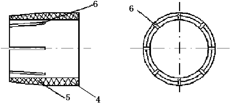
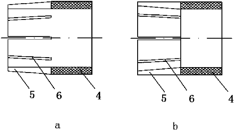
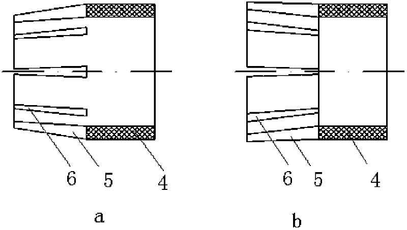
The invention relates to a high-adaptability composite material pipe joint. At least one end of a composite material pipe is a conical connecting section and is of the shape of an outer cone or an inner cone. A plurality of slits are circumferentially and evenly arranged. At the same time, a metallic taper pipe and a metallic tightening taper sleeve are arranged. The three sections of the metallic taper pipe are respectively a taper part, a male thread part and a connecting section part. The bottom diameter of a male thread is slightly larger than the outer diameter of the composite material pipe; the diameter of the small end of the taper part is equal to the inner diameter of the composite material pipe; the length of the taper part is equal to the depth of the slits of the composite material pipe; the small end of the metallic tightening taper sleeve is provided with inner taper, which is consistent with the total taper of the metallic taper pipe and the composite material pipe; the diameter of the small end of the metallic tightening taper sleeve is equal to the outer diameter of the composite material pipe; and the large end of the metallic tightening taper sleeve is provided with a female thread, which is matched with the male thread of the metallic taper pipe. The high-adaptability composite material pipe joint has good universality, economy and adaptability, the process is simple and reliable, the implementation is simple and flexible, joint schemes can be designed aiming at composite material pipes which are made of different materials, have different wall thicknesses and are used under different stress conditions, and the practicability and the applicability are high.

Description

technical field [0001] The invention relates to a high-adaptability composite material pipe fitting joint, which is a design proposal for a composite material pipe component joint. Suitable and especially suitable for complex space truss structures designed with thick-walled composite material tube members. The invention also relates to the design scheme and connection method of the highly adaptable composite material pipe joint. Background technique [0002] Composite pipes (such as carbon fiber pipes, glass fiber pipes, etc.) have been commercially produced in large quantities, but the material of composite pipes is not suitable for machining, and it is difficult to achieve the joints required by complex structures. At present, the design of joints of composite pipe members is divided into four categories according to materials and molding processes: one is short fiber molded joints, that is, joints are formed at the same time when composite pipe members are formed. This...

Claims


Application Information

Patent Timeline
Patent Type & Authority Applications(China)
IPC IPC(8): F16L19/02F16L13/10
Inventor 杨德华吴庆国陈昆新李国平
Owner NANJING INST OF ASTRONOMICAL OPTICS & TECH NAT ASTRONOMICAL OBSE
Why Eureka
Try Eureka