
Multimode occulting antenna with stable phase center

A phase-centered and stable technology, applied in the direction of antenna, antenna support/installation device, electrical components, etc., can solve the problems of insufficient coverage of GPS frequency range, limited overall antenna bandwidth, complex antenna feed network, etc. Frequency coverage, suppression of higher-order modes, effects of improving radiation characteristics

Active Publication Date: 2012-06-20
SPACE STAR TECH CO LTD
View PDF2 Cites 22 Cited by
  • Summary
  • Abstract
  • Description
  • Claims
  • Application Information

AI Technical Summary

Problems solved by technology

The advantage of this kind of antenna is that it can realize the coverage of various special shape patterns through the phase change of each array element of the antenna, but the beamforming antenna array needs to realize the signal excitation of different phases for each array element of the antenna, which leads to the complexity of the antenna feeding network and the The phase of the array changes greatly in the wide-angle range, and the stability of the phase center is poor. Accurate calibration of the phase center is required. Moreover, due to the narrow bandwidth of the phase-shifting network, the overall bandwidth of the antenna is greatly limited, and it cannot fully cover GPS, BD- 2. Frequency range of GALILEO and GLONASS

Method used


Image

  • Multimode occulting antenna with stable phase center
  • Multimode occulting antenna with stable phase center
  • Multimode occulting antenna with stable phase center

Examples


Embodiment

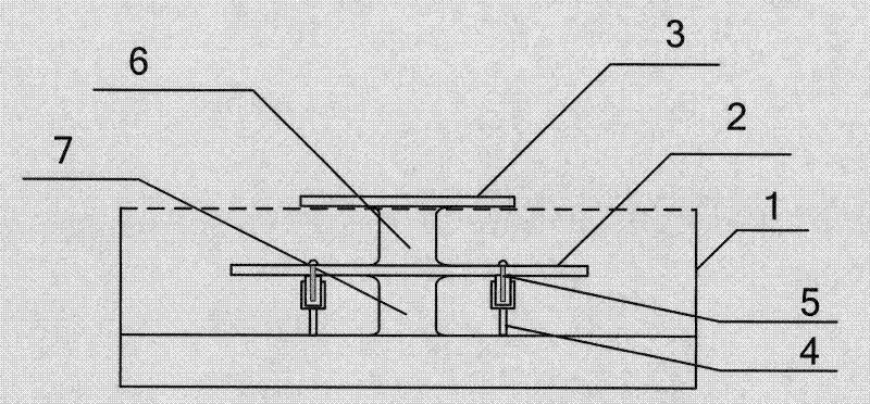
[0040] 1. The cavity height of the reflection cavity 1 is 35mm, and the cavity diameter is 160mm;

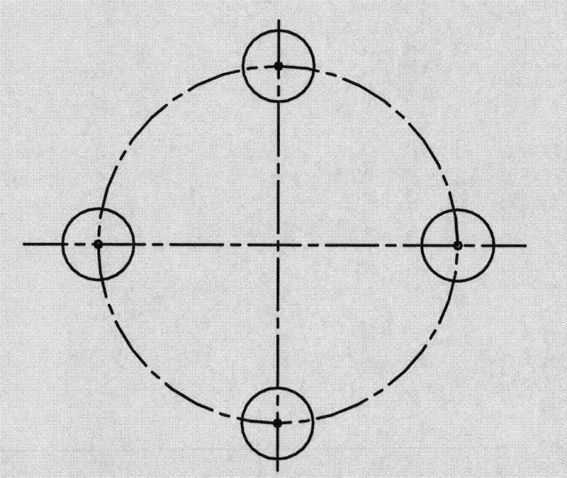
[0041] 2. The diameter of patch 3 on the radiating surface is 68 mm, and the thickness is 2 mm. There are four circular holes evenly distributed along the same circle on the radiating surface patch. The diameter of the circular holes is 6 mm. ;

[0042] 3. The height of the first support column 6 is 15mm, and the diameter is 10mm. The height of the second support column 7 is 16mm, and the diameter is 10mm; The lower patch 2 is threaded and crimped through the first support column 6 and the second support column 7;

[0043] 4. Four feeding probe sleeves 4 are uniformly distributed on the circumference, with a diameter of 46mm. The four supporting columns of the feeding probe sleeves (the metal column at one end of the metal seat 42) are metal cylinders with a height of 8mm and a diameter of 3mm. The barrel (cylindrical cavity at one end of the metal seat 42) is a metal cylindri...


PUM


Abstract

A multimode occulting antenna with a stable phase center comprises a reflection cavity, a lower radiation paster, an upper radiation paster, four feed probe sleeves, four feed probe inner cores and two support columns. Each feed probe sleeve comprises a metal seat and filler, one end of the metal seat is a metal column, the other end of the metal seat is a cylindrical metal cavity, and the filler is used for filling the cylindrical cavity of the metal seat. The sleeve-shaped probes are coupled with feed through four points, probes are uniformly distributed on the circumference, an aerial radiation paster consists of an upper layer and a lower layer, the lower layer is coupled with the feed through the sleeve-shaped probes, the upper layer is coupled with the feed through the lower radiation paster, the middle is supported by the metal support columns, and the reflection cavity is of a round bowl-shaped structure and higher than the upper radiation paster. The occulting antenna is excellent in performance and structure, simple and reliable in process, wide in frequency band, capable of meeting use requirements of a GPS (global positioning system), BD-2, GALILEO and GLONASS, wide in beam coverage, high in gain, stable in phase center, excellent in axial ratio performance, and applicable to a precise obscuration detection system and other high-precision detection systems.

Description

technical field [0001] The invention relates to an occultation antenna with a stable multi-mode phase center, which is suitable for occultation detection of precision satellites, drones, airships and other aircraft and other high-precision detection systems, and belongs to the technical field of high-precision detection antennas. Background technique [0002] In the late 1980s, foreign countries began to study a new method of detecting the earth's atmospheric environment based on GPS satellite radio signals: GPS radio signals are affected by atmospheric refraction when passing through the earth's atmosphere, and the propagation path is bent, resulting in The signal phase produces a delay, and by measuring these delays to obtain information such as temperature, pressure, humidity, and electron density in the atmosphere, this method is called radio occultation measurement technology. In order to improve the accuracy of occultation detection and inversion, a global Navigation S...

Claims


Application Information

Patent Timeline
Patent Type & Authority Applications(China)
IPC IPC(8): H01Q1/12H01Q1/36H01Q19/17
Inventor 刘宁民李时良池卿华阎凯李景贵郭文嘉
Owner SPACE STAR TECH CO LTD
Learn More