Circularly polarized differential feed patch antenna

An electric patch and circular polarization technology, applied in the field of antennas in the field of wireless communications, can solve problems affecting antenna radiation performance, amplitude and phase imbalance, loss, etc.

Active Publication Date: 2012-06-20
广州锦峰信息技术有限公司
View PDF4 Cites 12 Cited by
  • Summary
  • Abstract
  • Description
  • Claims
  • Application Information

AI Technical Summary

Problems solved by technology

If a single-ended antenna is interconnected with a differential circuit, it is necessary to add a balun in the middle for unbalanced to balanced conv...

Method used


Image

  • Circularly polarized differential feed patch antenna
  • Circularly polarized differential feed patch antenna
  • Circularly polarized differential feed patch antenna

Examples


Embodiment

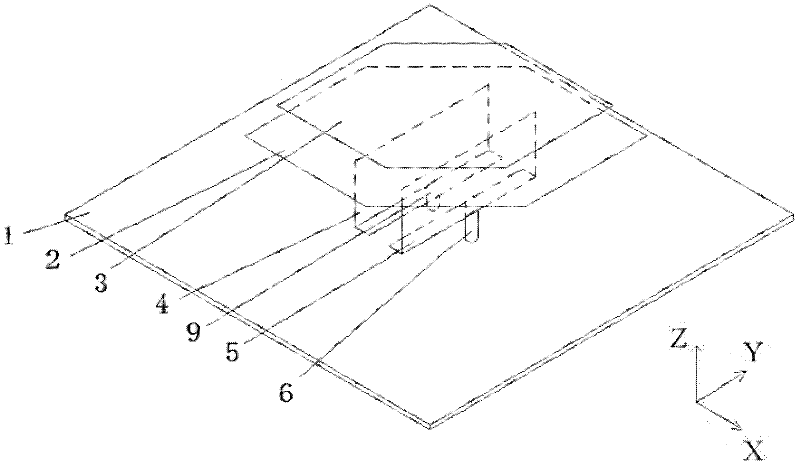
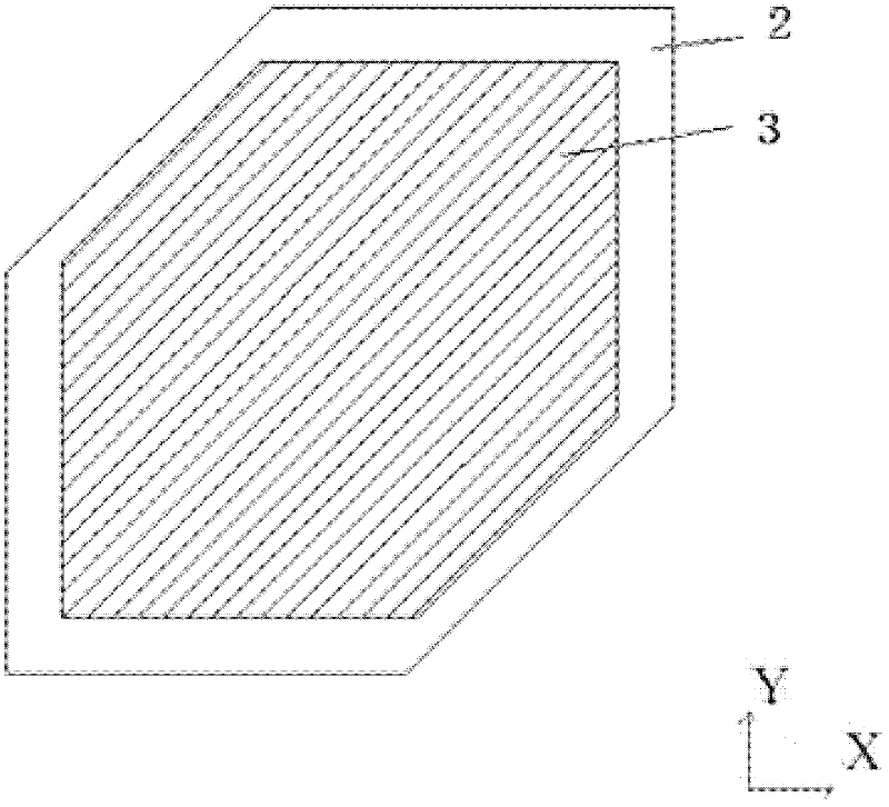
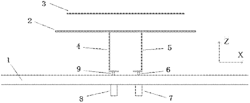
[0038]Both the first radiation patch 2 and the second radiation patch 3 are formed by cutting two diagonal corners of a square in parallel. The center frequency of the antenna is designed to be 2.2GHz. In the first radiation patch 2, the distance between the opposite sides of the square is 60mm, which corresponds to 0.44 times λo, where λo is the wavelength of free space. In the second radiation patch 3, the distance between the opposite sides of the square is 50 mm, which is a passive element. The vertical distance between the first radiation patch 2 and the horizontal substrate is 19 mm, which is approximately equal to 0.14λo. The distance between the first radiation patch 2 and the second radiation patch 3 is 5 mm. The first radiating patch 2 is fed differentially by a first L-shaped feed electrode plate 4 and a second L-shaped feed electrode plate 5, while the second radiating patch 3 is fed by electromagnetic coupling. Two diagonal corners of the first radiation patch 2 ...


PUM


Abstract

The invention discloses a circularly polarized differential feed antenna, comprising a radiation patch on the upper surface, two L-shaped feed panels, and a horizontal substrate on the lower surface, wherein the upper radiation patch comprises a first lower radiation patch and a second upper radiation patch which are spaced by a certain distance by an isolation foam; the first radiation patch is larger than the second radiation patch, two L-shaped feed panels are directly connected with the first radiation patch in the radiation patch on the upper surface, each L-shaped feed electrode panel is respectively connected with the horizontal substrate on the lower surface and an SMA connector by a probe, and the L-shaped feed panels are excited by a pair of differential signals. The impedance bandwidth and the axial ratio bandwidth are widened and the lower-level crossed polarization and stable direction diagram and gain can be seen on the work frequency band. The scheme can be used in the more and more popular radio frequency differential circuit and system.

Description

technical field [0001] The present invention relates to an antenna in the field of wireless communication, in particular to a circularly polarized patch antenna. Background technique [0002] In recent years, radio communication technologies such as radar, global positioning system, and cellular communication have developed rapidly. The ever-increasing demand for radiocommunication has led more and more researchers to invest in the innovative development of radiocommunication systems. In a radio communication system, the antenna is a core element. Compared with linearly polarized antennas, circularly polarized antennas have the advantages of wider receiving and transmitting azimuths, better mobility, and better weather adaptability, so they are more widely used in wireless communications. [0003] In recent years, the radio frequency identification technology (Radio Frequency Identification, referred to as RFID) industry has developed faster and faster, and it has a wide r...

Claims


Application Information

Patent Timeline
IPC IPC(8): H01Q1/36H01Q21/24
Inventor 章秀银代鑫张洪林
Owner 广州锦峰信息技术有限公司
Why Eureka
Try Eureka