Technology and equipment for manufacturing vacuum heat insulation vessel

A technology for vacuum insulation and manufacturing equipment, which is applied in the direction of manufacturing tools, metal processing equipment, drinking vessels, etc. It can solve the problems of easy air leakage, impact on the service life of the thermos cup, and the shape limitation of the thermos cup, so as to prolong the heat preservation time and seal The effect of better performance and longer service life

Inactive Publication Date: 2012-06-27
苏州雷嘉电子科技有限公司
View PDF7 Cites 10 Cited by
  • Summary
  • Abstract
  • Description
  • Claims
  • Application Information

AI Technical Summary

Problems solved by technology

When vacuuming, a thin copper tube is welded on the bottom of the shell in advance. This thin copper tube is the joint for vacuuming. After reaching the set vacuum pressure, the copper tube can be cut with vacuum shears, and the vacuum is closed at the same time. Therefore, there is a small broken thin copper tube at the bottom of the outer layer. In order to cover the copper tube, a plastic or stainless steel bottom cover is usually placed on the bottom of the outer layer, which lacks a sense of integrity in appearance and also has more processing technology. One process increases material cost and processing cost
In terms of heat preservation effect, although it has been vacuumed, after a period o...

Method used


Image

  • Technology and equipment for manufacturing vacuum heat insulation vessel
  • Technology and equipment for manufacturing vacuum heat insulation vessel
  • Technology and equipment for manufacturing vacuum heat insulation vessel

Examples


Embodiment 1

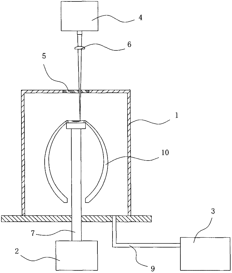
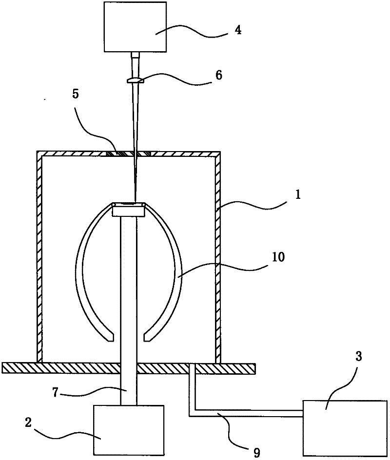
[0029] Embodiment one: see figure 1 , 2 As shown, a manufacturing equipment for vacuum heat preservation vessels includes a vacuum chamber 1, a turntable 2, a vacuum pump 3 and a laser welding device 4. The vacuum chamber 1 is provided with a cavity for accommodating a vessel to be processed, and a laser window is provided on the top of the vacuum chamber 1. 5. There is a focusing lens 6 between the laser welding equipment 4 and the vacuum chamber 1, the emitting end of the laser welding equipment 4 corresponds to the laser window 5, and the turntable 2 is located below the vacuum chamber 1 , the turntable 2 is composed of a rotating motor and the support rod 7 connected to the output shaft of the rotating motor, the top of the support rod 7 matches the inner bottom surface of the vessel to be processed, and the support rod 7 extends into the vacuum In the chamber 1, the vessel to be processed is buckled upside down on the support rod 7, and the position of the opening to be ...


PUM


Abstract

The invention discloses a technology and equipment for manufacturing a vacuum heat insulation vessel. The equipment is characterized by comprising a vacuum cavity, a turntable, a vacuum pump and laser welding equipment, wherein the top of the vacuum cavity is provided with a laser window; the turntable is positioned below the vacuum cavity; a supporting rod is arranged on the top of the turntable, the supporting rod extends into the vacuum cavity, and the vessel to be processed is reversely buckled on the supporting rod; and the vacuum pump is connected with the vacuum cavity through a vacuum pipeline. The technology comprises the following steps of: (1) respectively forming an inner container and a shell by stretching, and welding the inner container and the shell to form a body; (2) reversely buckling the body on the supporting rod on the top of the turntable; (3) putting the supporting rod into the vacuum cavity; (4) rotating the turntable, vacuumizing, and performing laser welding; and (5) rotating the turntable for one circle to finish welding, wherein the diameter of the inner cavity of the middle part of the manufactured body is greater than that of a top opening. The vacuumizing port at the bottom of the body in the vacuum cavity is welded by using laser beams, so that direct welding under a vacuumizing environment is realized; and the bottom of the equipment is flat, so the attractiveness and the heat insulation property are promoted.

Description

technical field [0001] The invention relates to a manufacturing process and equipment of a thermal insulation vessel, in particular to a manufacturing process and equipment of a vacuum thermal insulation vessel. Background technique [0002] The thermal insulation cup slows down the speed of heat exchange between the liquid or solid carried in the cup and the outside world by setting a thermal insulation layer. Depending on the material of the thermal insulation layer, it has a lot of influence on the thermal insulation effect. There are two kinds of common insulation layers, one is the insulation layer filled with foam (usually polyurethane foam), and the other is the vacuum insulation layer. Among them, the latter vacuum-type thermos cup is superior to the former foam-type thermos cup in terms of thermal insulation performance, and the manufacturing process is relatively more complicated. The specific process steps are: [0003] The inner layer and the outer layer are str...

Claims


Application Information

Patent Timeline
IPC IPC(8): A47J41/02A47G19/22A45F3/18B23K26/20B23K26/12B23K26/21
Inventor 黄志强
Owner 苏州雷嘉电子科技有限公司
Why Eureka
Try Eureka