Optical-display uterine lifting device

A technique of lifting a uterus and a light source, applied in obstetrics and gynecology instruments, medical science, endoscope, etc., can solve the problems of no lighting function, low service life, difficult surgical operation, etc., and achieve safe and convenient surgical operation and structural design. Reasonable and applicable effect

Active Publication Date: 2012-06-27
HANGZHOU KANGJI MEDICAL INSTR
View PDF3 Cites 7 Cited by
  • Summary
  • Abstract
  • Description
  • Claims
  • Application Information

AI Technical Summary

Problems solved by technology

But it also has the problem of no lighting function, the palace is not in place, and the operation is prone to deviation
[0005] Chinese Utility Model Patent No. ZL2009201483225 discloses a "high temperature and high pressure resistant endoscope". Although the endoscope is equipped with an illumination fiber bundle between the inner tube and the outer tube, it cannot be directly applied to the structure of the palace lifter middle
[0006] Chinese Invention Patent Application No. ZL2010101753683 discloses a "Visible Obtaining Ring Forceps". Although it includes a connecting rod composed of a long tube and an optical fiber guide, and an optical fiber is arranged in the optical guide, it is also not directly applicable to lifting the uterus. in the structure of the device
[0007] In addition, there are other patent applications for inventions and utility models of multifunctional uterine lifters or medical devices with light guide fibers, but their structural design is not reasonable enough.
At the same time, the structures disclosed in the prior art cannot be simply combined, even with the addition of common knowledge, otherwise it will lead to the lifting of the uterus not in place, or the volume of the uterine lifting device will be large, or the service life will be low, or the surgery will be difficult. Difficulty, or a combination of the above disadvantages

Method used


Image

  • Optical-display uterine lifting device
  • Optical-display uterine lifting device
  • Optical-display uterine lifting device

Examples


Embodiment 1

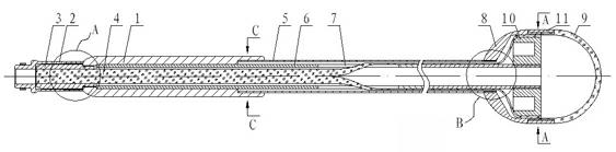
[0033] Embodiment 1: see figure 1 — Figure 8 , the present embodiment is illustrated by taking a convex palace lifter and two waist-shaped grooves as an example.

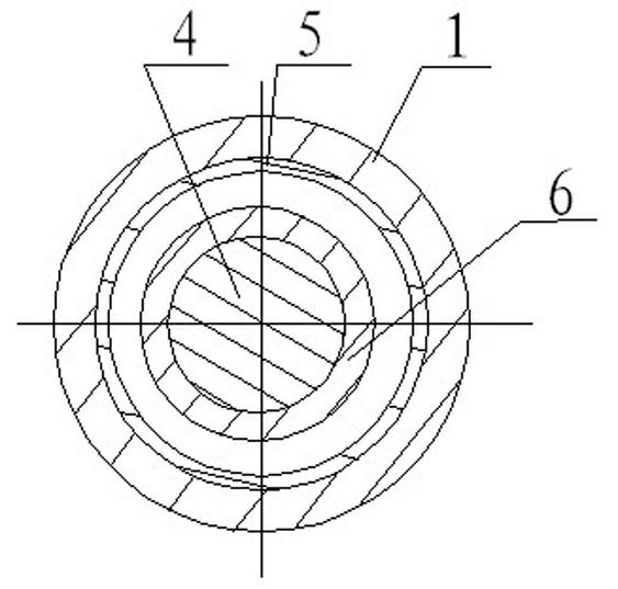
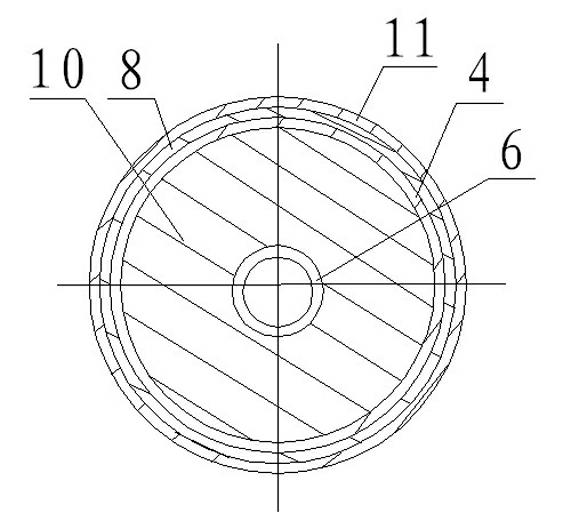
[0034] This embodiment is mainly composed of a handle 1, a light source connecting seat 2, a light guide fiber 4, an outer tube 5, an inner tube 6, a waist groove 7, a spherical seat 8, a transparent spherical cover 9 and a fixing sleeve 10.

[0035] In this embodiment, the inner tube 6 is provided with a waist-shaped groove 7, and the light-guiding fiber 4 is inserted into the inner tube 6, respectively passes through the two waist-shaped grooves 7, and is glued and fixed on the outer surface of the inner tube 6 in a circular shape; The inner tube 6 is set into the handle 1 and fixed by gluing, the outer tube 5 is set outside the inner tube 6, and is welded and fixed with the handle 1; the screw sleeve 3 is set into the inner tube 6 and fixed with the handle 1, and the light source connecting seat 2 is set into ...

Embodiment 2

[0042] Example 2: see Figure 9 — Figure 11 , the present embodiment is illustrated by taking the concave palace lifter and two waist-shaped grooves as examples.

[0043] This embodiment includes a handle 1 , a light source connection seat 2 , a screw sleeve 3 , a light guide fiber 4 , an outer tube 5 , an inner tube 6 , a waist-shaped groove 7 , a spherical seat 8 and a cervical fixing sleeve 12 .

[0044]In this embodiment, the inner tube 6 is provided with a waist-shaped groove 7, and the light guide fiber 4 is inserted into the inner tube 6 and passes through the waist-shaped groove 7 and is glued and fixed to the outside of the inner tube 6 in a circular shape; the inner tube 6 is inserted into the handle 1 Gluing and fixing, the outer tube 5 is inserted into the circular light guide fiber 4 and welded with the handle 1, the screw sleeve 3 is inserted into the inner tube 6 and the handle 1 is screwed and fixed, the light source connecting seat 2 is inserted into the scr...


PUM


Abstract

The invention relates to an optical-display uterine lifting device which is mainly applicable to gynecological pathological examination and hysterectomy. The optical-display uterine lifting device comprises a hollow handle, an inner pipe, an outer pipe and a spherical seat, and is characterized by being further provided with a light source connecting seat, an optical fiber, a fixing sleeve and atleast one waist-shaped groove, wherein the light source connecting seat has a hollow structure and is positioned at one end of the inner pipe; the waist-shaped groove is arranged on the inner pipe and is positioned in the middle of the inner pipe; the optical fiber passes through the waist-shaped groove and is fixed with the outer surface of the inner pipe; one end of the optical fiber is arranged in the inner pipe, and the other end of the optical fiber is arranged between the spherical seat and the fixing sleeve; the two ends of the inner pipe extend outside the two ends of the outer pipe; one end of the inner pipe is positioned in the spherical seat, and the other end of the inner pipe is arranged in the light source connecting seat; and the light source connecting seat, the handle, the outer pipe and the spherical seat are sequentially arranged on the same axis. The optical-display uterine lifting device is reasonable and simple in structural design, is capable of lifting the uterus in place, and is safe and convenient in surgical operation, good in effect and wide in application scope.

Description

technical field [0001] The invention relates to a uterine lifter, in particular to a light-display uterine lifter, which is mainly suitable for gynecological pathological examination and hysterectomy, and belongs to the field of medical equipment. Background technique [0002] Hysterectomy is mainly based on abdominal surgery. In recent years, with the development of minimally invasive laparoscopic surgery technology, it has basically replaced traditional laparotomy. Hysterectomy must pass a systematic pathological examination. Hysterectomy mainly includes subtotal hysterectomy, total hysterectomy, and extensive hysterectomy. In the prior art, there are many uterine lifting devices used in laparoscopic hysterectomy, wherein the uterine lifting cup is a rigid cup-shaped device that is inserted into the vagina from the vaginal opening and encases the cervix to lift the uterus. In the actual operation process, because the laparoscope enters the human body from the abdominal ca...

Claims


Application Information

Patent Timeline
Patent Type & Authority Applications(China)
IPC IPC(8): A61B17/42A61B1/303A61B1/07
Inventor 张震宇钟鸣申屠银光
Owner HANGZHOU KANGJI MEDICAL INSTR
Why Eureka
Try Eureka