Machine tool fixture

A machine tool fixture and machine base technology, which is applied in the direction of clamping, manufacturing tools, metal processing machinery parts, etc., can solve the problems of accumulative error of machine base rework positioning, product collision damage, and inability to detect the exact size of the machine base from its center, etc.

Active Publication Date: 2012-06-27
CSR ZHUZHOU ELECTRIC CO LTD
View PDF9 Cites 4 Cited by
  • Summary
  • Abstract
  • Description
  • Claims
  • Application Information

AI Technical Summary

Problems solved by technology

[0006] However, since the workpiece is set on the base plate 1, the workpiece blocks the center point of the base plate 1, and is positioned only by setting the center coordinates of the base plate 1 and the horizontal machining center coincidently, so the above-mentioned machine tool fixture cannot detect the distance from the outer end surface of the machine base to its center. Therefore, after the processing is completed, the machine base needs to be unloaded from the horizontal machining center and transferred to a three-coordinate measuring instrument. Through the three-coordinate measuring instrument, a new coordinate system is established on the product to detect the relevant dimensions of the machine base. , if the test is unqualified, it is necessary to go back to the machine tool for rework or repair
[0007] It can be seen from the above processing and testing process that the horizontal machining center in the prior art cannot directly detect the space-related dimensions of the product. Only the combination of the horizontal machining center and the three-coordinate detector can complete the processing and testing of the motor frame. There is a secondary positioning and benchmark conversion in the processing of the type machining center and the detection of the three-coordinate detector, and there will be certain errors in the detection results. Large, it is easy to cause bump damage to the product, and there are accumulated errors in the positioning of the base after repeated rework, etc.

Method used


Image

  • Machine tool fixture
  • Machine tool fixture
  • Machine tool fixture

Examples


Embodiment Construction

[0030] The core of the present invention is to provide a machine tool fixture, which can realize the positioning and clamping of the workpiece, and can meet the needs of workpiece processing and detection, reduce the detection error of the workpiece, and improve the processing accuracy and manufacturing efficiency.

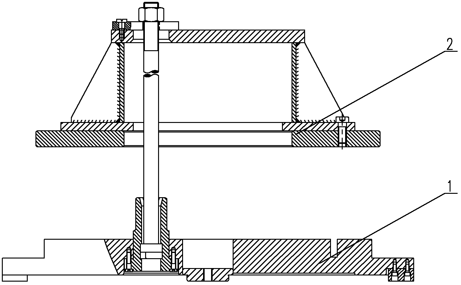
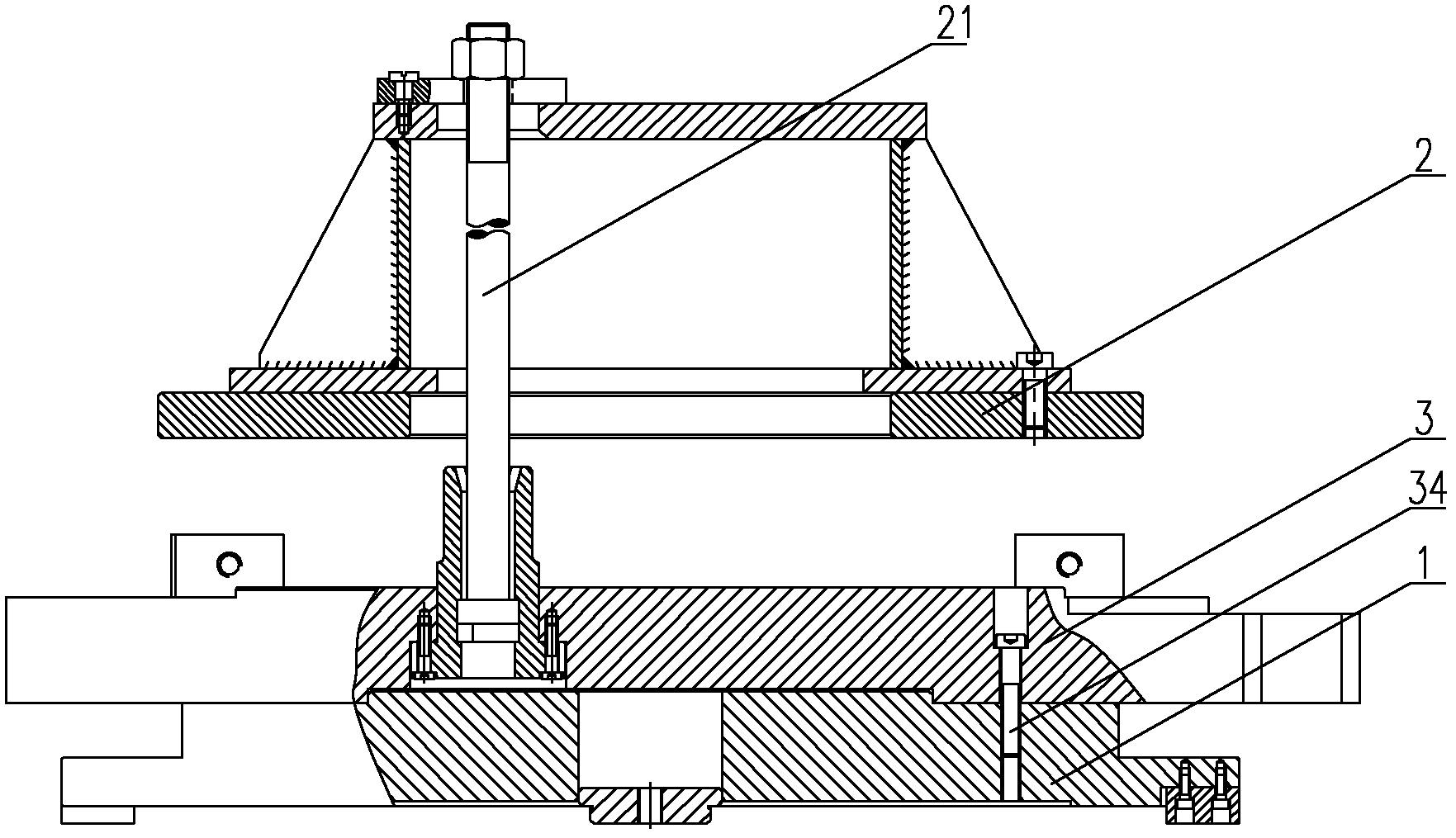
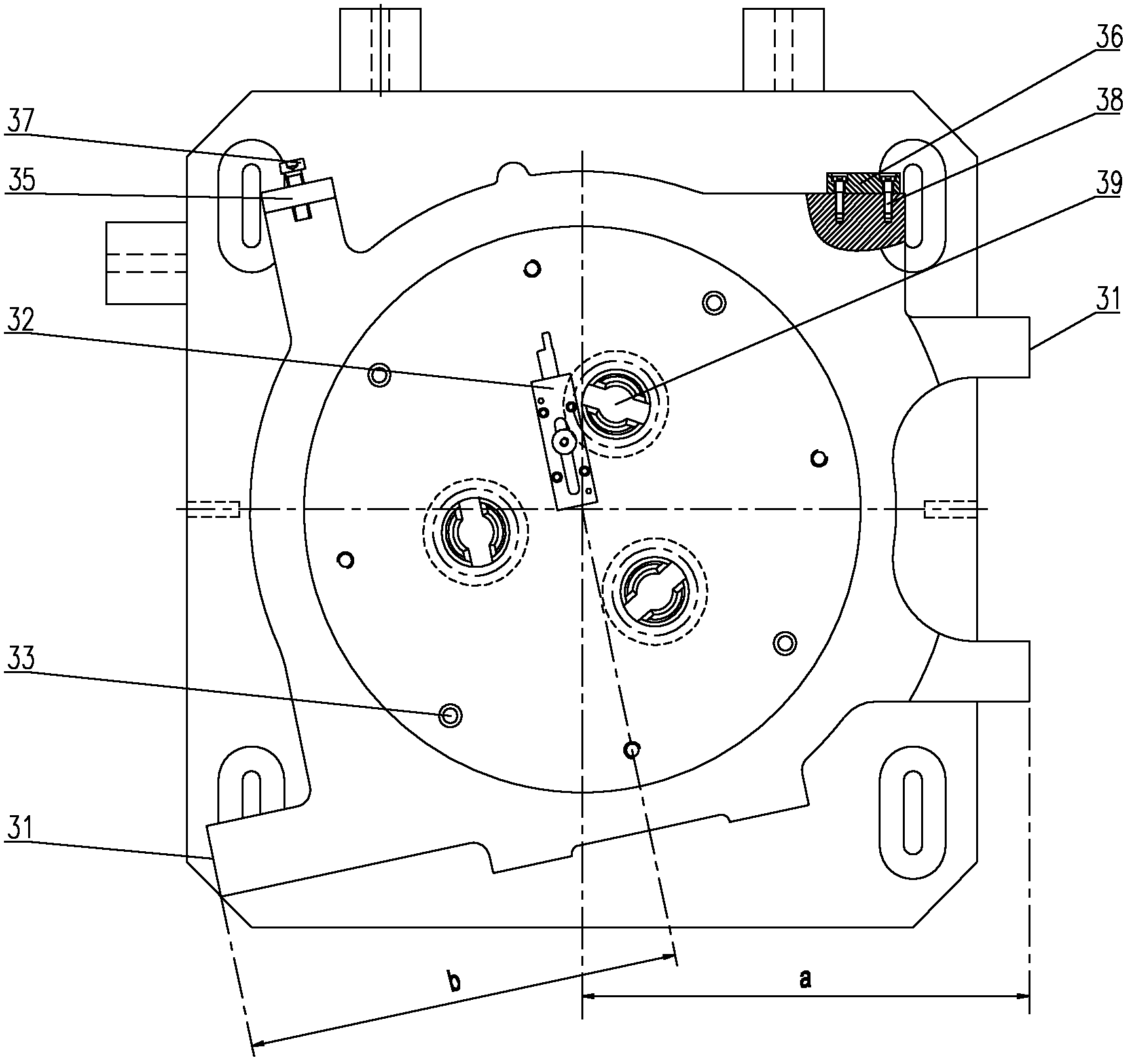
[0031] Please refer to figure 2 and image 3 , figure 2 It is a front view of a specific embodiment of the machine tool fixture provided by the present invention; image 3 for figure 2 top view.

[0032] In a specific embodiment, such as figure 2 and image 3 As shown, the present invention provides a machine tool fixture, which includes a base plate 1, a positioning plate 3 and a pressing device 2, the base plate 1 is used to support the workpiece, the pressing device 2 is used to fix the workpiece, and the positioning plate 3 is arranged on the base plate 1 Between the clamping device 2, the positioning plate 3 provides a detection reference plane 31 f...


PUM


Abstract

The invention discloses a machine tool fixture, which comprises a bottom plate (1), a clamping device (2) and a positioning plate (3), wherein the bottom plate (1) is used for supporting a workpiece, the clamping device (2) is used for fixing the workpiece, and the positioning plate (3) provides a detecting reference surface (31) for the workpiece and is arranged between the bottom plate (1) and the clamping device (2). The center of the positioning plate (3) and the center of the workpiece are arranged on the axis of a spindle of a machine tool for machining the workpiece, and the distance from the center of the positioning plate (3) to the reference surface (31) is a reference distance. By the aid of the machine tool fixture, a machining coordinate system can be provided for the workpiece, the reference surface in the same coordinate system can also be provided, and the requirements of the workpiece on machining and detecting are met. Compared with the prior art, the machine tool fixture has the advantages that the machining coordinate system and a detecting coordinate system do not need to be built respectively, so that manufacture errors caused by coordinate transformation are avoided, and workpiece machining precision and workpiece machining efficiency are greatly improved.

Description

technical field [0001] The invention relates to the technical field of mechanical manufacturing, processing and detection, in particular to a machine tool fixture. Background technique [0002] The fixture is a device used to fix the processing object in the process of mechanical manufacturing so that it occupies the correct position to accept construction or inspection. Fixtures can be divided into welding fixtures, inspection fixtures, assembly fixtures, machine tool fixtures, etc., among which machine tool fixtures are the most common. [0003] When machining a workpiece on a machine tool, in order to make the surface of the workpiece meet the technical requirements of the size, geometric shape, and position accuracy with other surfaces specified in the drawing, the workpiece must be positioned and clamped by machine tool fixtures before processing. Machine tool fixtures are usually composed of positioning elements, clamping devices, tool setting guide elements, indexing...

Claims


Application Information

Patent Timeline
Patent Type & Authority Applications(China)
IPC IPC(8): B23Q3/00
Inventor 杨学军石江
Owner CSR ZHUZHOU ELECTRIC CO LTD
Why Eureka
Try Eureka