Long bar stock fixture for lathe

A long bar and material clip technology, applied in the field of workpiece clamping fixtures, can solve the problems of large workpiece size, short workpiece clamping range, long overhang length, etc., to achieve the effect of ensuring machining accuracy

Inactive Publication Date: 2012-06-27
广州机床厂有限公司
View PDF5 Cites 7 Cited by
  • Summary
  • Abstract
  • Description
  • Claims
  • Application Information

AI Technical Summary

Problems solved by technology

Due to the characteristics of the clamping of ultra-long bars, the scope of the workpiece clamping part is relatively short, the overhang length is long, and the effect of the gravity of the workpiece itself, the farthe

Method used


Image

  • Long bar stock fixture for lathe
  • Long bar stock fixture for lathe
  • Long bar stock fixture for lathe

Examples


Embodiment Construction

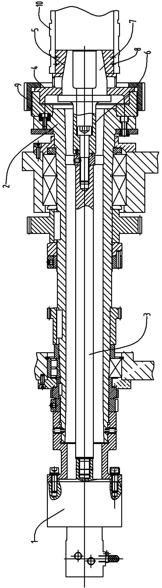
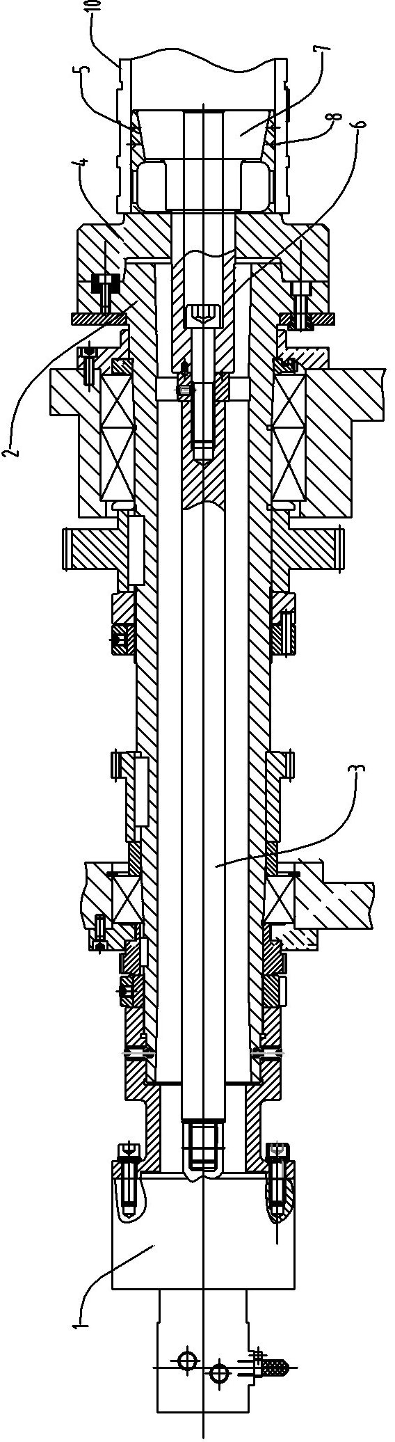
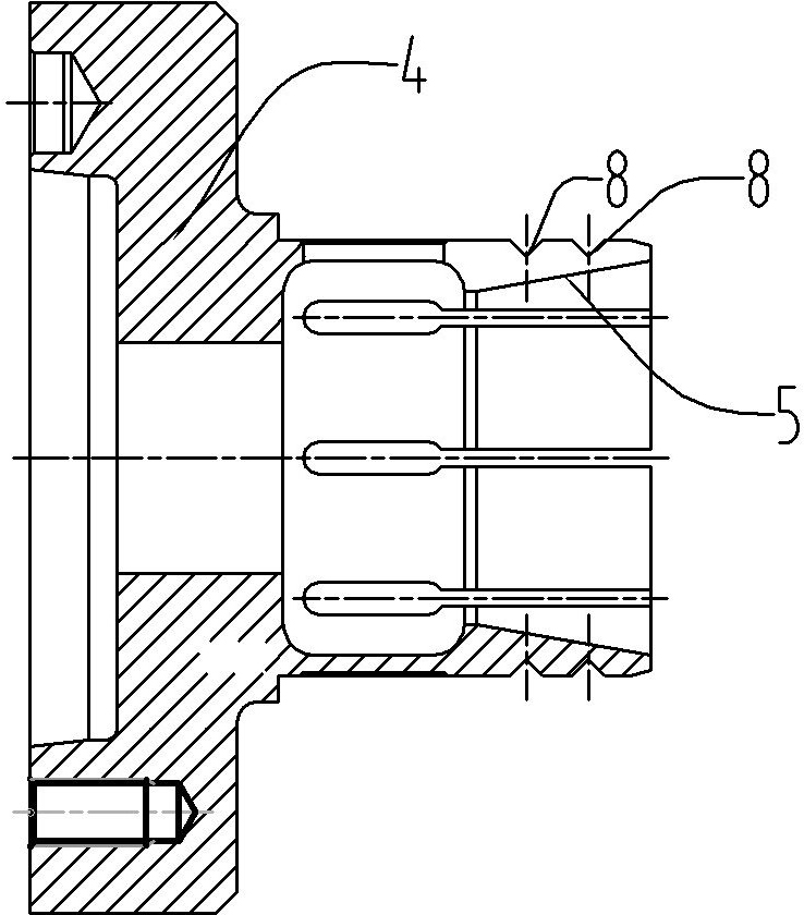
[0012] Such as figure 1 , a long bar material clamp for a lathe, including a clamp body 2 fixed on the spindle head 1, a pull bar 3 is installed inside the clamp body, a spring expansion sleeve 4 is installed on the end of the clamp body, and fixed by a lock nut 9, The end of the spring expansion sleeve is provided with a tapered inner hole 5, the tapered inner hole can face the pull bar, the end of the pull bar is connected to the outer cone mandrel 6, and the end of the outer cone mandrel is provided with a tapered head 7, the diameter of the tapered head Shrinking, facing the tapered inner hole, the other end of the pull bar is connected to the hydraulic cylinder that drives its expansion and contraction, through the hydraulic cylinder to push the pull bar, the tapered head of the outer cone mandrel can be inserted into the tapered inner hole to support the spring expansion sleeve open.

[0013] The above-mentioned long bar fixture for the lathe, when clamping the workpiec...


PUM


Abstract

The invention discloses a long bar stock fixture for a lathe. The end part of a fixture body is fixedly provided with a spring expanding cover, and the end part of the spring expanding cover is provided with a tapered inner hole. The end part of a pull rod is connected with an outer-cone core shaft, and the end part of the outer-cone core shaft is provided with a tapered head inserted into the tapered inner hole. The other end of the pull rod is connected with a hydraulic cylinder driving the pull rod to stretch out and draw back, and the tapered head of the pull rod is pushed by the hydraulic cylinder so as to open the spring expanding cover. When the fixture clamps a workpiece, the end part of the spring expanding cover is inserted into a shaft hole of the long bar stock workpiece, the hydraulic cylinder is used for driving the pull rod to move, and the tapered head of the end part of the outer-cone core shaft causes the spring expanding cover to be expanded and tightly supported on the inner hole of the workpiece, so that the workpiece is clamped. The fixture is simple and convenient for clamping and is matched with a self-centering center frame and a tailstock with a special cone plug for use. Only the coaxiality of three points, namely the spring expanding cover, the self-centering center frame and the tailstock is ensured, the clamping precision of an overlong bar stock can be ensured, and therefore the processing precision of the workpiece is ensured.

Description

technical field [0001] The invention relates to a workpiece clamping fixture used on a lathe, in particular to a fixture for clamping and processing super-long bar workpieces with shaft holes. Background technique [0002] Large CNC lathes with extended flat bed are especially suitable for processing workpieces with large diameter and super long bar (length-to-diameter ratio exceeding 10 or more). However, it is difficult to clamp such workpieces. To make the clamping of such workpieces stable and reliable, It is the difficulty in the design of special fixtures for this type of lathe. Due to the characteristics of the clamping of super-long bars, the range of the workpiece clamping part is relatively short, the overhang length is long, and the effect of the gravity of the workpiece itself, the farther away from the chuck, the more the workpiece hangs downward, resulting in the size of the processed workpiece. The head is big and the tail is thin and it is difficult to guar...

Claims


Application Information

Patent Timeline
IPC IPC(8): B23Q3/12
Inventor 梁洁瑜赵韶东杨习军黄敢莫家麟梁祖欣钟文东
Owner 广州机床厂有限公司
Why Eureka
Try Eureka