
Low-density and high-strength cement paste

A high-strength cement slurry and low-density technology, applied in the direction of drilling composition, chemical instruments and methods, etc., can solve the problems that the cement slurry cannot maintain the design density, the comprehensive performance of the cement slurry deteriorates, and cannot meet the engineering needs, etc., to achieve The thickening time is adjustable, the formation pollution is small, and the effect of widening the application range

Active Publication Date: 2013-12-04
BC P INC CHINA NAT PETROLEUM CORP +1
View PDF2 Cites 0 Cited by
  • Summary
  • Abstract
  • Description
  • Claims
  • Application Information

AI Technical Summary

Problems solved by technology

[0003] 1. Because the floating beads have thin walls and low strength, they are easily broken under high pressure conditions, causing the cement slurry to fail to maintain the design density. As the pressure increases, the number of broken floating beads gradually increases, making the density of the cement slurry increase and flow Poor performance, bringing unsafe factors to cementing construction;
[0004] 2. Due to the density of ordinary floating beads (0.7g / cm 3 Left and right) are relatively high, and the density value of cement slurry is limited within the effective strength range. A large number of studies have shown that the density of low-density cement slurry containing ordinary floating beads can only be 1.35g / cm 3 Above, if it is lower than this density, the comprehensive performance of the cement slurry will be deteriorated and cannot meet the engineering needs

Method used


Image

  • Low-density and high-strength cement paste
  • Low-density and high-strength cement paste
  • Low-density and high-strength cement paste

Examples


Embodiment 1

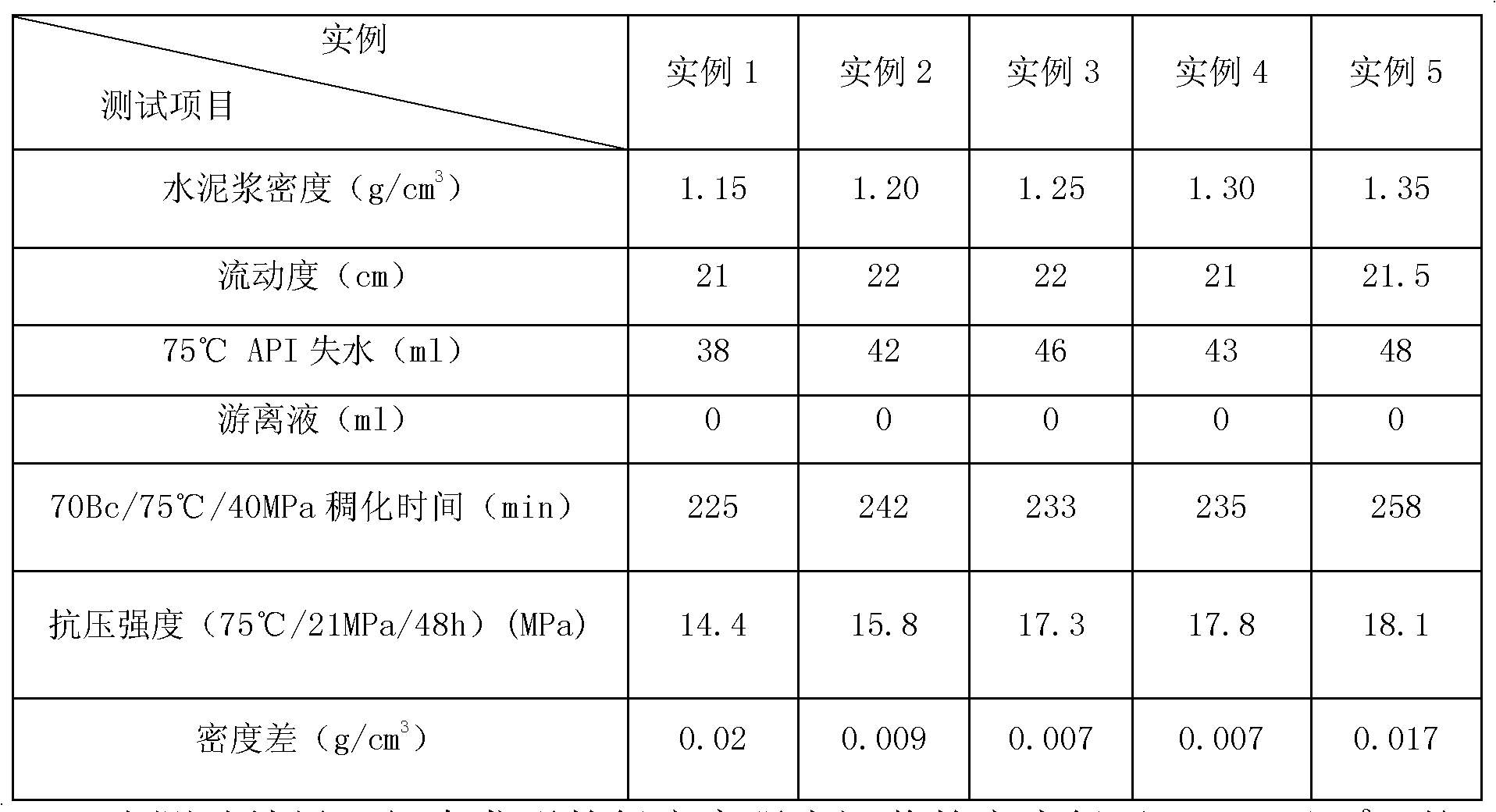
[0023] 240 parts of G grade portland oil well cement, 110 parts of fly ash, 100 parts of HGS18000 glass microspheres, 31.6 parts of micro silicon, 7.2 parts of G33S, 2.9 parts of USZ, 327 parts of water are mixed in proportion and then used on a rotational viscometer with 4000 Stir at rpm speed for 60 seconds, and test various properties according to API specifications, and the test results are shown in Table 1.

Embodiment 2

[0025] 250 parts of Portland G grade oil well cement, 112 parts of fly ash, 90.5 parts of HGS18000 glass microspheres, 29 parts of microsilicon, 7.2 parts of G33S, 2.9 parts of USZ, 318 parts of water are mixed in proportion and then used on a rotational viscometer with 4000 Stir at rpm speed for 60 seconds, and test various properties according to API specifications, and the test results are shown in Table 1.

Embodiment 3

[0027] 260 parts of Portland G grade oil well cement, 143 parts of fly ash, 81 parts of HGS18000 glass microspheres, 30.2 parts of microsilicon, 7.7 parts of G33S, 3.1 parts of USZ, 332 parts of water are mixed in proportion and then used on a rotational viscometer with 4000 Stir at rpm speed for 60 seconds, and test various properties according to API specifications, and the test results are shown in Table 1.


PUM

PropertyMeasurementUnit
diameteraaaaaaaaaa
compressive strengthaaaaaaaaaa
densityaaaaaaaaaa

Abstract

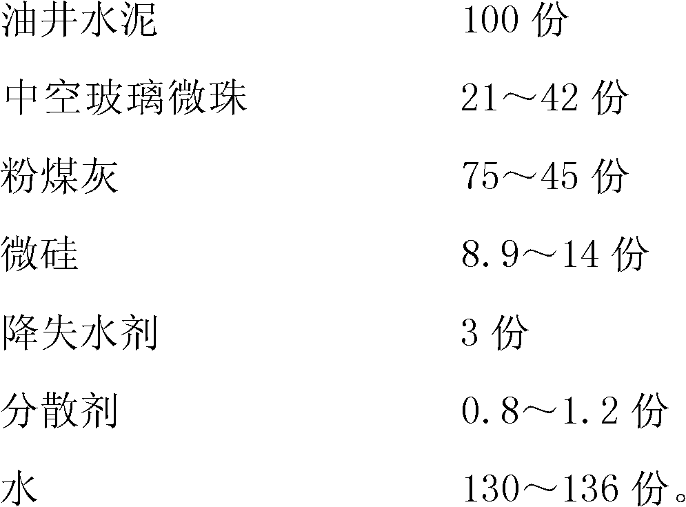
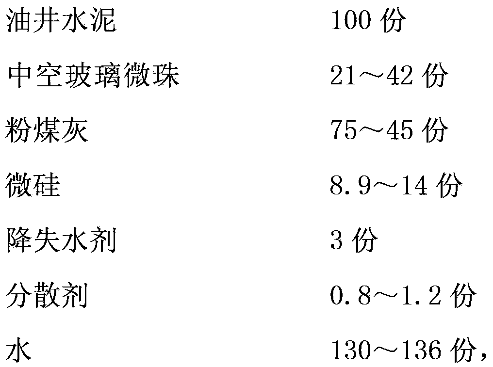
The invention discloses low-density and high-strength cement paste, which is applied to cementing of wells tending to leak under a low pressure. The cement paste is prepared from the following components in parts by weight: 100 parts of oil well cement, 21-42 parts of hollow glass microbeads, 75-45 parts of coal ash, 8.9-14 parts of micro silicon, 3 parts of a filtration-reducing agent, 0.8-1.2 parts of a dispersing agent and 130-136 parts of water. In the cement paste, glass microbeads are taken as main lightening materials, so that the density of low-density cement paste is lowered to 1.15-1.35 g / cm<3>, and the application arrange of the low-density cement paste is widened; by compactly piling cement particles, coal ash particles, glass microbead particles and micro silicon particles, the percentage of solid-phase particles is increased, and cement stone is dense, has high strength, high penetration resistance, high sedimentation stability and contribution to preventing of rush, and is free from concentration; and the cement paste does not contains any early strength admixture, the strength is enhanced by fully depending on compact piling of particles, the cement paste can be mixed with any fluid loss agent without damaging the fluid loss effect, and pollution on stratum is low.

Description

technical field [0001] The invention relates to the field of oil field drilling engineering, in particular to a low-density, high-strength cement slurry for well cementing in low-pressure wells that are prone to leakage. Background technique [0002] With the intensification of oil exploration and development, the number of low-pressure leaky wells has gradually increased. Using low-density cement slurry to balance well cementing is one of the effective measures to prevent leakage, improve cementing quality and protect oil and gas layers. However, the current low-density cement slurry uses ordinary floating beads as a lightening agent, and this cement slurry has the following disadvantages: [0003] 1. Because the floating beads have thin walls and low strength, they are easily broken under high pressure conditions, causing the cement slurry to fail to maintain the design density. As the pressure increases, the number of broken floating beads gradually increases, making the...

Claims


Application Information

Patent Timeline
Patent Type & Authority Patents(China)
IPC IPC(8): C09K8/473
Inventor 陈光钟福海宋元洪陈斌任建良韩革委
Owner BC P INC CHINA NAT PETROLEUM CORP
Learn More