Bender hydraulic system

A hydraulic system and bending machine technology, applied in the direction of mechanical equipment, fluid pressure actuators, servo motors, etc., can solve the problems of complex back pressure in the unloading circuit, low control stability valve group, and bulky products, etc., to achieve The effect of improving the stability of work progress

Inactive Publication Date: 2012-06-27
NANJING ALPHA ELECTRO HYDRAULIC TECH +1
View PDF5 Cites 6 Cited by
  • Summary
  • Abstract
  • Description
  • Claims
  • Application Information

AI Technical Summary

Problems solved by technology

[0005] This technology solves the problems that the unloading circuit of the hydraulic control system of the existing bending machine is relatively complicated, the stability of the back pressure control is not high, the installation of the valve group is troublesome, the product is bulky, and the power density ratio is low. Reliable hydraulic system of bending machine with adjustable back pressure

Method used


Image

  • Bender hydraulic system
  • Bender hydraulic system
  • Bender hydraulic system

Examples


Embodiment Construction

[0012] The technology will be further described below in conjunction with the accompanying drawings.

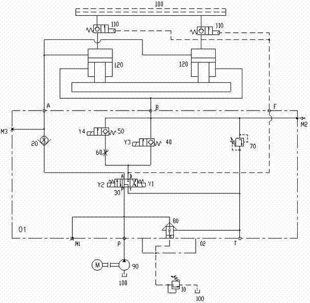
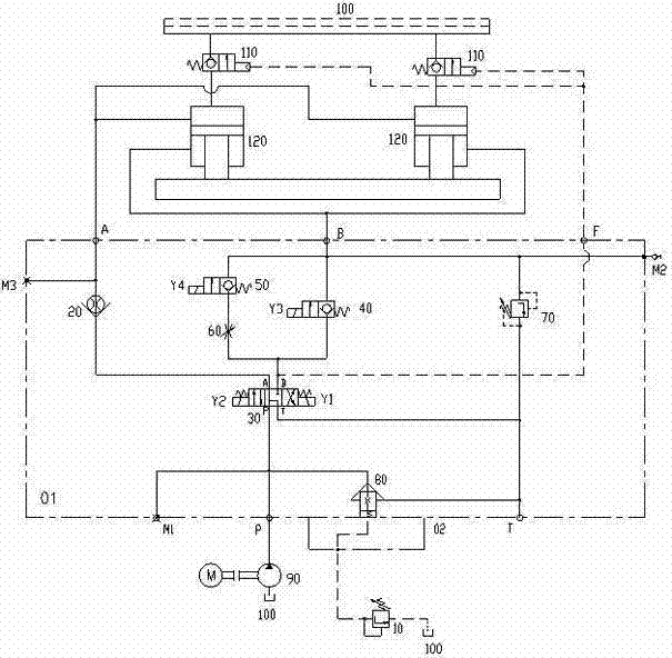
[0013] see figure 1 The hydraulic system of the bending machine shown in , includes an oil pump 90 , an oil tank 100 , and a three-position four-way reversing valve 30 . The filling valve 110 is connected between the oil tank 100 and the upper cavity of the oil cylinder 120 . The oil outlet of the oil pump 90 is connected to the oil tank through the two-way cartridge valve 80. The remote pressure regulating valve 10 is connected to the control port of the two-way cartridge valve 80 .

[0014] The P port of the three-position four-way reversing valve 30 is connected to the oil outlet of the oil pump 90, the B port is connected to the lower chamber of the oil cylinder through the first electromagnetic reversing valve 40, and the A port is connected to the upper chamber of the oil cylinder through the throttling check valve 20. Port B of the three-position four-way reversing ...


PUM


Abstract

The invention provides a bender hydraulic system which has simple structure, reliable control and back pressure being capable of being adjusted at will, aiming at solving the problems that an unloading circuit of the traditional bender hydraulic control system is more complex, back pressure control stability is low, a valve group is troublesome to mount, a product is heavy and power density ratio is low. The bender hydraulic system provided by the invention comprises an oil pump, an oil tank, a three-position three-way reversing valve, wherein a charging valve is connected between the oil tank and the upper cavity of a cylinder; the oil outlet of the oil pump is connected with the oil tank by virtue of a two-way cartridge valve; the port P of the three-position four-way reversing valve 30 is connected with the oil outlet of the oil pump, the port B of the three-position four-way reversing valve 30 is connected with the lower cavity of the cylinder by virtue of a first electromagnetic directional valve 40; the port B is also connected with the control port of the charging valve; the port A of the three-position four-way reversing valve 30 is connected with the upper cavity of the cylinder by virtue of a throttling check valve 20; and the port B is also connected with the lower cavity of the cylinder by virtue of a second electromagnetic directional valve 50 and a throttling valve 60.

Description

technical field [0001] The technology relates to a bending machine hydraulic control system, specifically, a non-electro-hydraulic servo synchronous bending machine hydraulic control system, especially suitable for torsion axis synchronous, hydraulic synchronous and other types of bending machine hydraulic control. Background technique [0002] At present, the principle of the hydraulic control system of the domestic torsion axis synchronous bending machine is similar, and it has basically remained unchanged for decades. The hydraulic components all adopt the domestic common plate installation valve. The entire hydraulic control valve group has a large mass and a low power density ratio. [0003] The unloading circuit of the hydraulic system of the existing bending machine is relatively complicated. [0004] In addition, in the hydraulic system of the existing bending machine, when the machine tool is fast down, the oil in the lower chamber of the oil cylinder is directly r...

Claims


Application Information

Patent Timeline
Patent Type & Authority Applications(China)
IPC IPC(8): F15B13/02F15B11/22B21D11/00
Inventor 余继军柳倩希陈华
Owner NANJING ALPHA ELECTRO HYDRAULIC TECH
Why Eureka
Try Eureka