Rowing motion compensation method for fiber optic gyroscope trapdown inertial navigation

A fiber optic gyroscope and motion compensation technology, applied in the field of inertial navigation, can solve problems such as loss of precision, achieve the effect of avoiding loss of precision and improving system performance

Inactive Publication Date: 2012-06-27
ZHEJIANG UNIV
View PDF3 Cites 11 Cited by
  • Summary
  • Abstract
  • Description
  • Claims
  • Application Information

AI Technical Summary

Problems solved by technology

Since the fiber optic gyroscope is essentially an angular rate gyroscope, it is necessary to convert the angular rate to an angular increment when using the angular increment to compensate the paddling motion. This conv

Method used


Image

  • Rowing motion compensation method for fiber optic gyroscope trapdown inertial navigation
  • Rowing motion compensation method for fiber optic gyroscope trapdown inertial navigation
  • Rowing motion compensation method for fiber optic gyroscope trapdown inertial navigation

Examples


Embodiment Construction

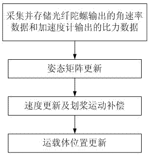
[0017] Paddle motion in inertial navigation refers to the combined motion of equal-frequency linear oscillations and angular oscillations on orthogonal axes. If the rapid attitude changes that occur between consecutive specific force decompositions are not considered, it will cause acceleration zero bias on the third axis, which will bring navigation errors and reduce navigation accuracy. Therefore, paddle motion compensation is required. The paddling effect compensation term is

[0018] ;

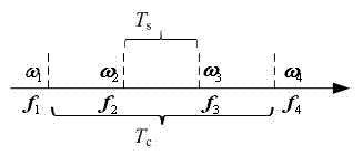
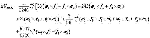
[0019] Since the output of the fiber optic gyroscope and the accelerometer is the angular rate signal and the specific force signal, it is impossible to directly apply the above formula to calculate the compensation item of paddling motion. The angular velocity and specific force changes of the carrier are fitted with a cubic parabola segmentally, and the paddling effect compensation term is converted into the expression form of angular velocity and specific force, which can improve the...


PUM


Abstract

The invention discloses a rowing motion compensation method for fiber optic gyroscope trapdown inertial navigation, which comprises the following steps of: collecting and storing angular rate data output by a fiber optic gyroscope and specific force output by an accelerometer; updating an attitude matrix; carrying out speed updating and rowing motion compensation, segmentedly fitting a change in the angular rate and the specific force of a carrier by using a cubic parabola, and directly utilizing the angular rate output of the gyroscope and the specific force output of the accelerometer to carry out rowing motion compensation; and updating a carrier position. According to the rowing motion compensation method for fiber optic gyroscope trapdown inertial navigation provided by the invention, the change in the angular rate and the specific force of the carrier is segmentedly fit, and a rowing effect compensation term is converted into a form expressed by the angular rate and the specific force, so that the precision loss brought by angular increment conversion is avoided, and the performance of a fiber optic gyroscope strapdown inertial navigation system is improved.

Description

technical field [0001] The invention relates to the field of inertial navigation, in particular to a method for padding motion compensation of optical fiber gyro strapdown inertial navigation. Background technique [0002] Navigation accuracy is an important index to measure the performance of navigation system. When the combined movement of equal-frequency oscillation and angular oscillation is performed on the orthogonal axis of the vehicle, that is, the paddling movement, if the rapid attitude change that occurs between successive specific force vector decompositions is not considered, the acceleration zero bias will be introduced. Thus affecting the navigation accuracy. [0003] To improve the navigation accuracy in large dynamic and harsh vibration environments, paddle motion compensation is required. The existing paddling motion compensation method uses angular increments, or both angular increments and angular rates to update the speed, and combining it with the gyr...

Claims


Application Information

Patent Timeline
IPC IPC(8): G01C21/16
Inventor 律新伟舒晓武刘承
Owner ZHEJIANG UNIV
Why Eureka
Try Eureka