Transmission gear contact pattern experimental facility

A transmission gear and contact spot technology, applied in the field of transmission gear contact spot experiment device, can solve the problems of low precision, large fluctuation, poor stability, etc., and achieve the effects of improving efficiency and quality, high degree of automation, and stable operation performance.

Active Publication Date: 2012-06-27
GIF RES CENT CHINA
View PDF7 Cites 5 Cited by
  • Summary
  • Abstract
  • Description
  • Claims
  • Application Information

AI Technical Summary

Problems solved by technology

However, the preliminary work of the current tooth surface contact spot detection experiment and the power supply during the experiment are usually done manually, that is, the transmission is driven by manual hand cranking. The existing problems are that the test process is time-consuming, inefficient, and input And the control of the output torque depends too much on the experience of skilled operators, often with low precision and poor stability, resulting in large differences and fluctuations between the experimental results and expected data

Method used


Image

  • Transmission gear contact pattern experimental facility
  • Transmission gear contact pattern experimental facility
  • Transmission gear contact pattern experimental facility

Examples


Embodiment

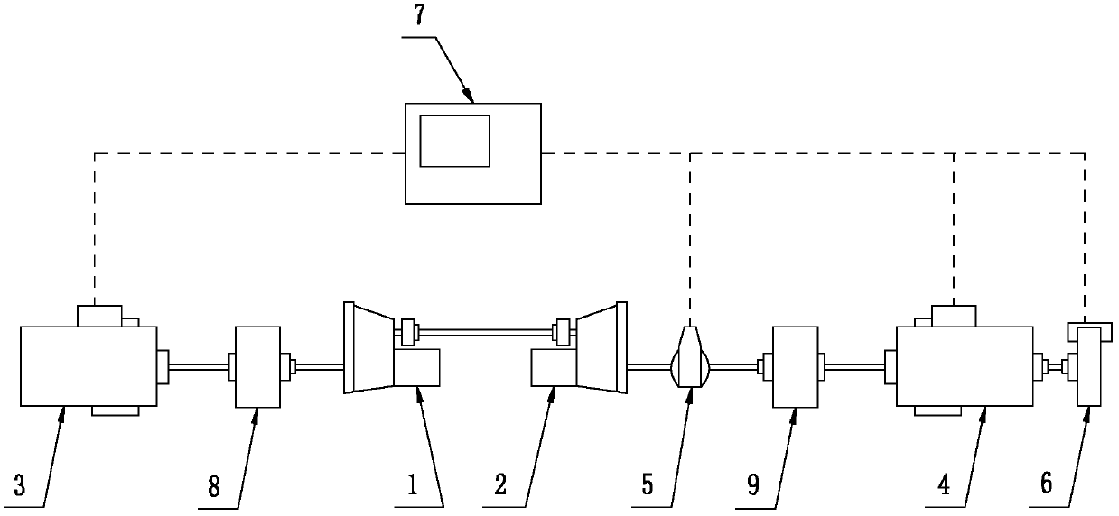
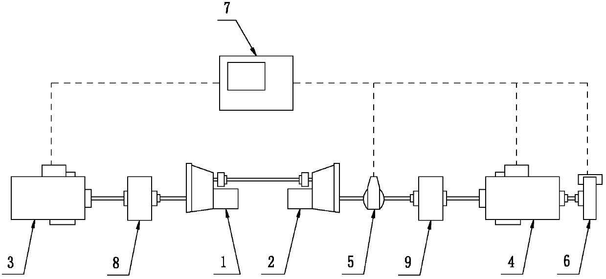
[0032] Example: Combine figure 1 Shown is a kind of specific embodiment of the transmission gear contact spot experimental device of the present invention, and it is made up of first test transmission 1, second test transmission 2, driving motor 3, dragging motor 4, torque sensor 5, motor brake 6 , PC controller 7, first reducer 8 and second reducer 9.

[0033] The output ends of the first and second test transmissions 1 and 2 are connected through the transmission shaft, the output shaft of the drive motor 3 is connected with the input end of the first speed reducer 8, and the output end of the first speed reducer 8 is connected through the transmission shaft Link to the input end of the first test transmission 1; the output shaft of the drag motor 4 is connected to the input end of the second speed reducer 9, and the output end of the second speed reducer 9 is connected to one end of the torque sensor 5 through the transmission shaft, and the torque The other end of the sen...


PUM


Abstract

The invention discloses a transmission gear contact pattern experimental facility, which comprises two test transmissions of which the output ends are connected through a transmission shaft, and is characterized by further comprising a driving motor, a dragging motor, a torsion sensor, a motor brake and a PC (Personal Computer) controller, wherein the output shaft of the driving motor is connected with the input end of the first test transmission; the output shaft of the dragging motor is connected with one end of the torsion sensor, the other end of the torsion sensor is connected with the input end of the second test transmission through the transmission shaft, and the tail end of the dragging motor is connected with the motor brake; and the driving motor, the dragging motor, the torsion sensor and the motor brake are all electrically connected with the PC controller. The transmission gear contact pattern experimental facility disclosed by the invention has the advantages of high automation degree, stabile performance, good detection precision, and capability of greatly increasing the efficiency and quality of a transmission gear contact pattern experiment.

Description

technical field [0001] The invention relates to a transmission gear contact spot test device. Background technique [0002] Hypoid gears are widely used in aviation industry, automobile industry and heavy mining equipment and other fields due to their large smooth running range, low sliding speed and high transmission efficiency. Especially with the rapid development of the automobile industry, the meshing quality requirements of the hypoid gears are getting higher and higher. In the field of automotive transmission technology, the gear tooth geometric parameters of all gear pairs are evaluated to see whether the contact spots are evenly and reasonably distributed, so as to optimize the NVH problems such as vibration and noise of the transmission. [0003] Tooth surface contact spots are one of the important indicators to measure the meshing quality of hypoid gears. The traditional detection of tooth surface contact spots is mainly based on visual judgment by experienced en...

Claims


Application Information

Patent Timeline
Patent Type & Authority Applications(China)
IPC IPC(8): G01M13/02
Inventor 芮敏谷叶水冯飞范鑫
Owner GIF RES CENT CHINA
Why Eureka
Try Eureka