

Direct-acting soft friction testing apparatus
A test device and direct-acting technology, which is applied in the field of measuring instruments, can solve the problem of inability to obtain real-time access to elastic material surface deformation and lubrication medium distribution rules in the contact area, and achieve the effect of simple structure and improved efficiency.
- Summary
- Abstract
- Description
- Claims
- Application Information
AI Technical Summary
Problems solved by technology
Method used
Image

Examples
Embodiment Construction
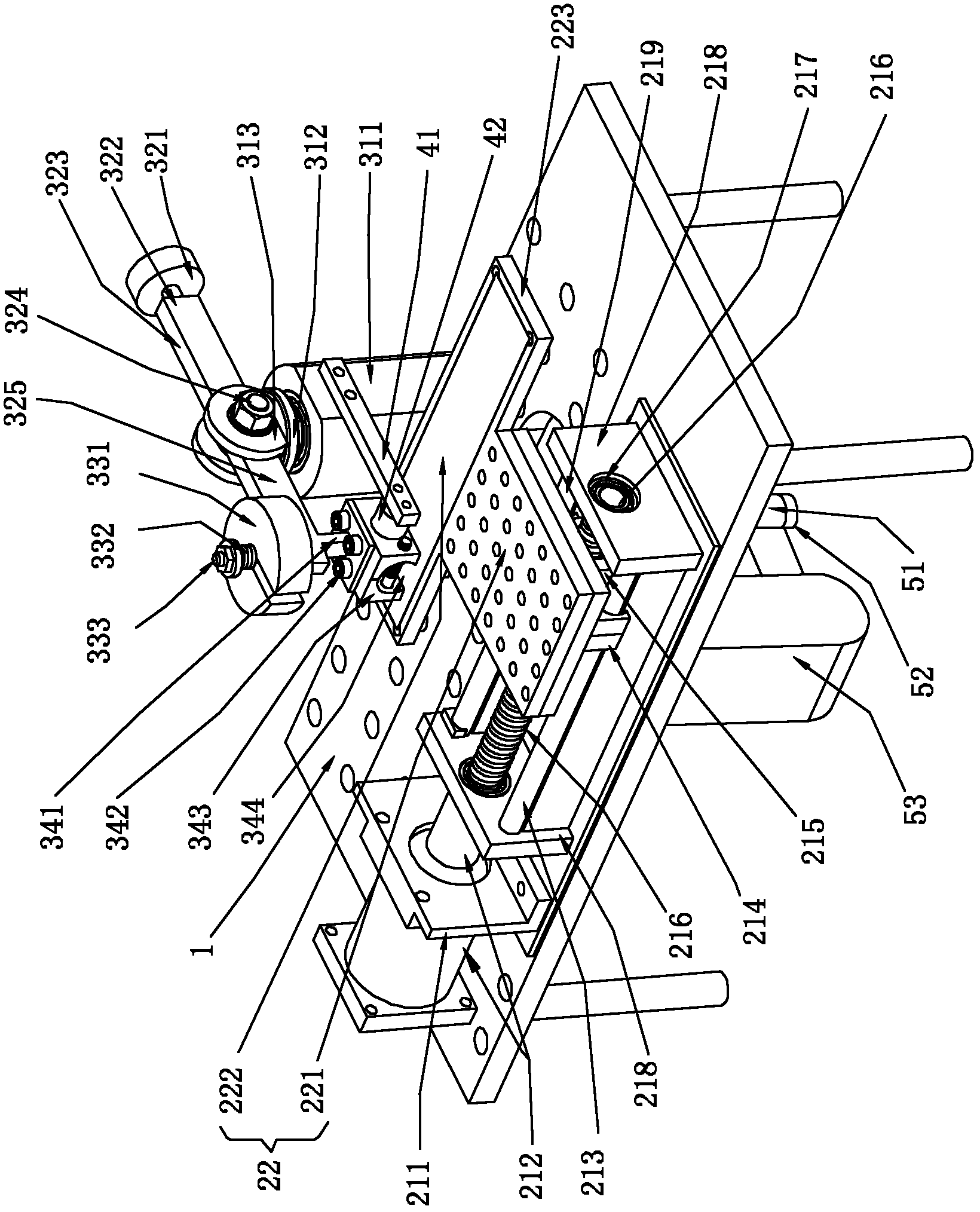
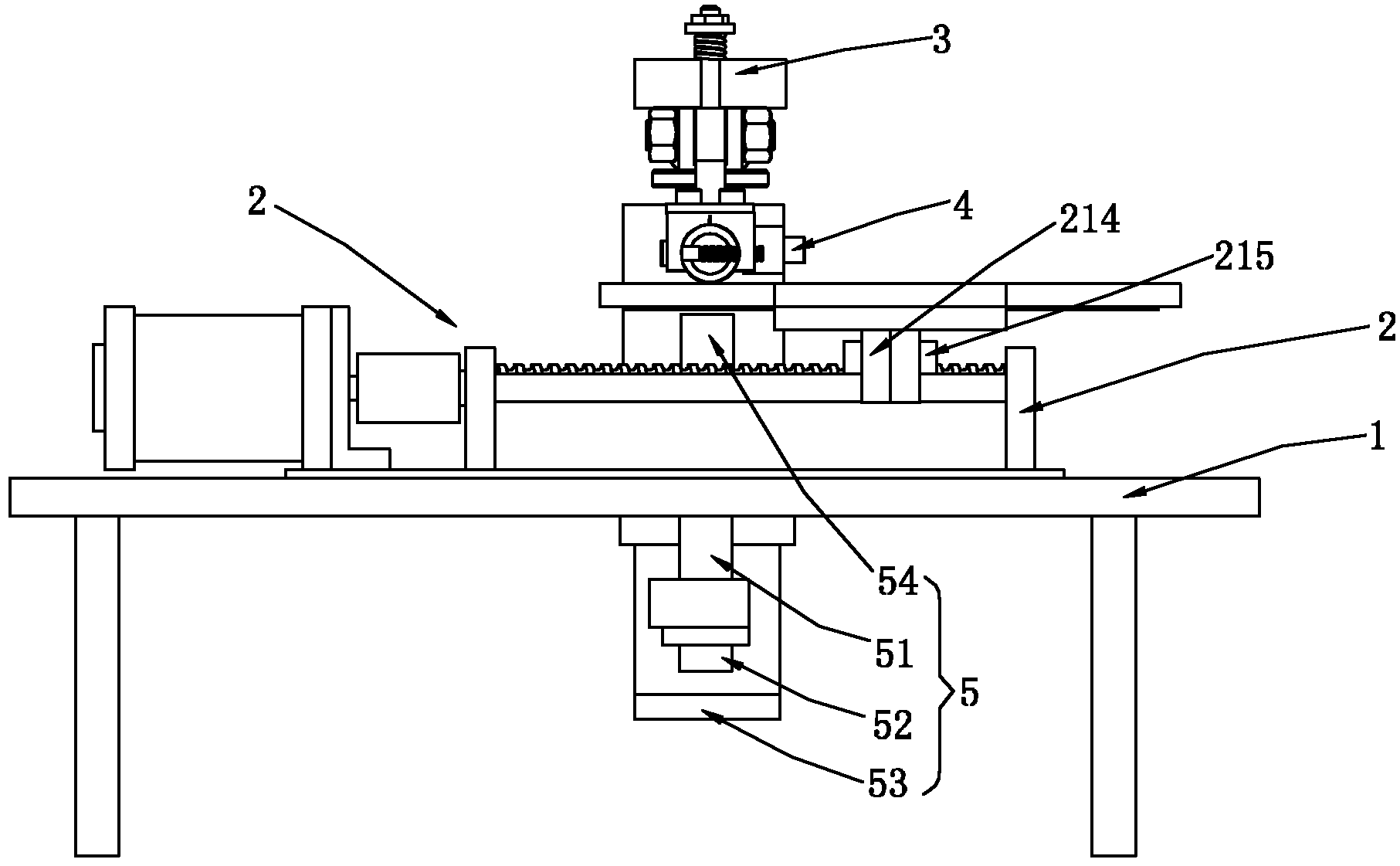
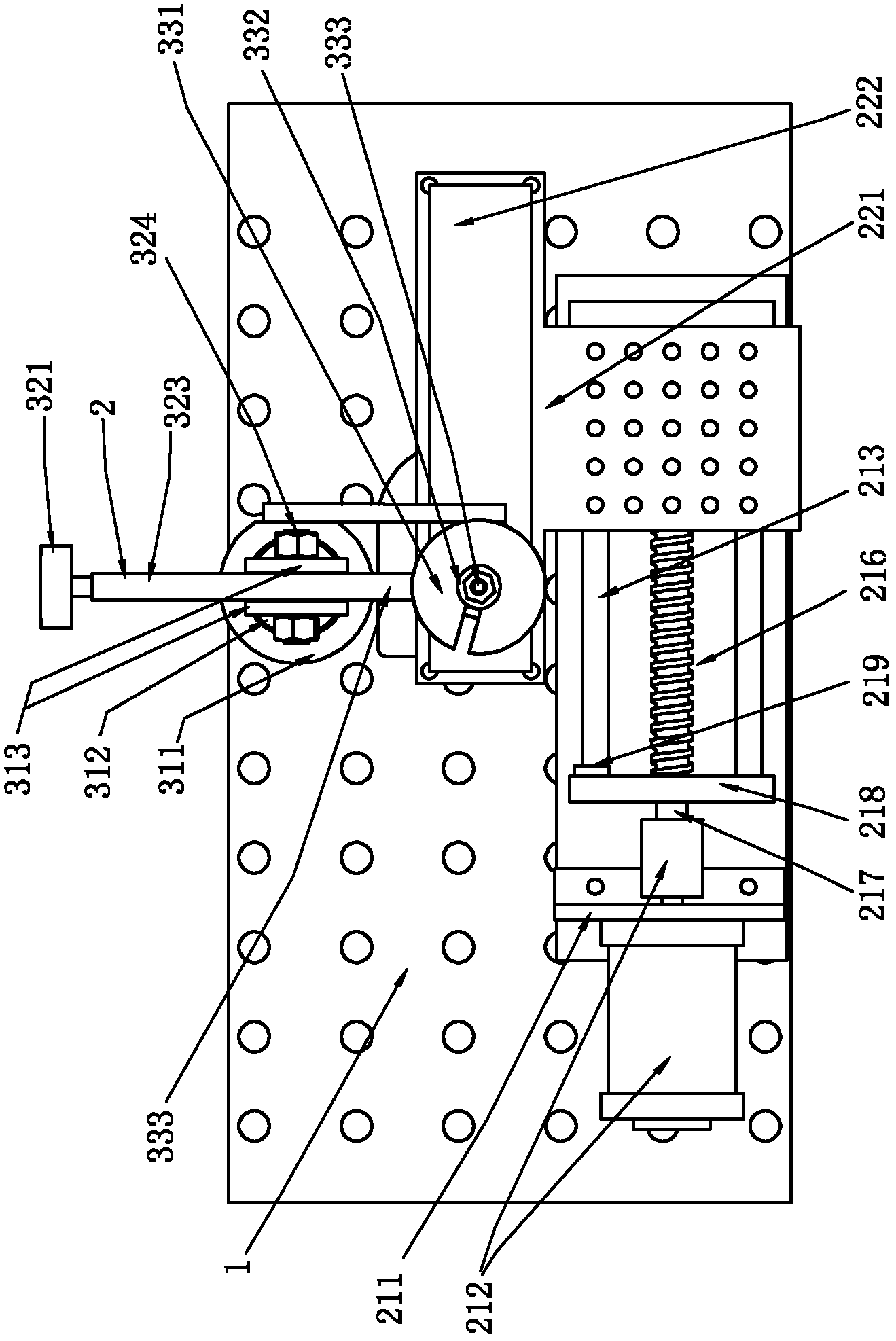
[0039]A kind of direct motion type soft friction testing device proposed by the present invention comprises: a supporting platform; a lower sample fixing frame, which is arranged on the upper part of the supporting platform, and is connected with a driving mechanism, and can be driven by the driving mechanism. Linear movement in the plane. The upper sample assembly is arranged on the upper part of the lower sample holder, and is connected with the loading mechanism capable of exerting downward pressure; the friction detection mechanism is arranged on the support platform, and is connected with the upper sample assembly connected; two samples with different elastic modulus are respectively fixed in the upper sample assembly and the lower sample holder, and the upper sample abuts against the lower sample through the loading mechanism Above, the friction force between the upper and lower samples is detected by the friction force detection mechanism.
[0040] In the present inven...
PUM
| Property | Measurement | Unit |
|---|---|---|
| Elastic modulus | aaaaa | aaaaa |
| Elastic modulus | aaaaa | aaaaa |
Abstract
Description
Claims
Application Information