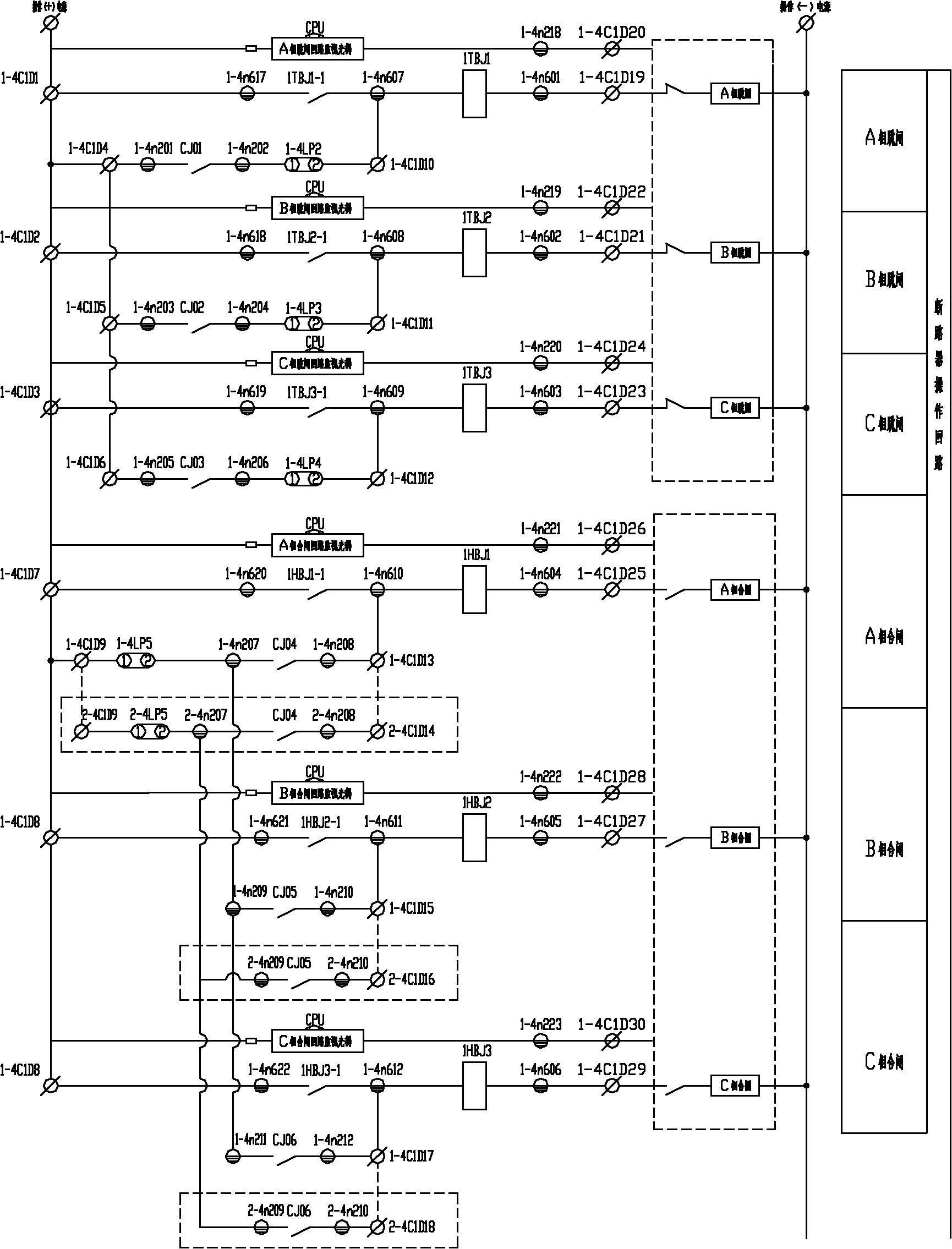
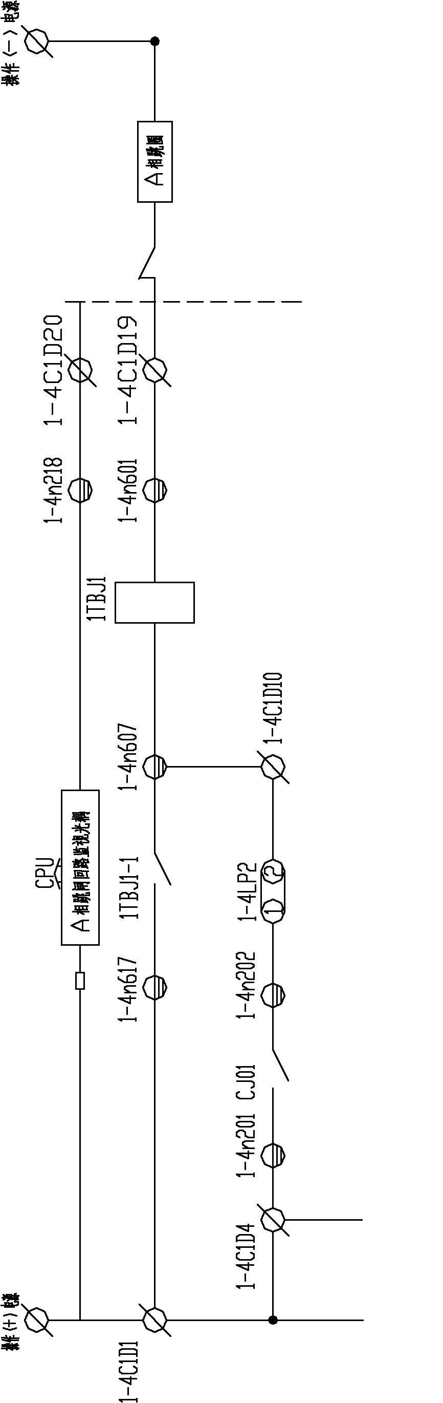
Circuit for determining lockout states of lockout relays
A state circuit and relay technology, applied in the direction of circuit breaker testing, etc., can solve problems such as damage to export relays, high equipment costs, and influence on power system safety and stability, and achieve the effect of eliminating influence
- Summary
- Abstract
- Description
- Claims
- Application Information
AI Technical Summary
Problems solved by technology
Method used
Image

Examples
Embodiment 1
[0030] Example 1, in an intelligent substation in Weifang, Shandong, the PRS7789 intelligent terminal equipment produced by Changyuan Shenrui Jibao Automation Co., Ltd. (formerly Shenzhen Nanrui Technology Co., Ltd.) is used. The intelligent terminal equipment has the function of export monitoring. The export relay adopts Panasonic DSP2a-DC24V relay, the large resistance adopts 48kΩ resistor, the current starting optocoupler adopts Toshiba TLP521, and the starting current is 8mA.
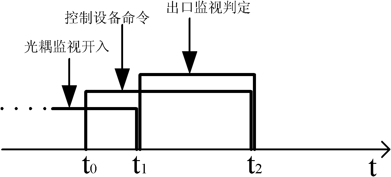
[0031] The smart terminal device monitors the status of the circuit breaker in real time. Taking the circuit breaker in position as an example, the determination strategy is as follows:
[0032] 1. The intelligent terminal equipment receives the trip command of the protection and measurement and control equipment. During the command extension time, the optocoupler monitors the input from 1 to 0, and when the command returns, the actual position of the circuit breaker is in the position, then the inte...
PUM
 Abstract
Description
Claims
Application Information