Light-emitting diode (LED) current detection and control circuit

A technology of control circuit and current detection, which is applied in the direction of electric lamp circuit arrangement, measurement of current/voltage, electric light source, etc., can solve the problems of complicated control method and increased circuit volume for current detection and control, etc.

Active Publication Date: 2012-06-27
SHENZHEN LINGQI SEMICON CO LTD
View PDF5 Cites 39 Cited by
  • Summary
  • Abstract
  • Description
  • Claims
  • Application Information

AI Technical Summary

Problems solved by technology

The peak current and output current ripple of continuous current mode inductors are small, and relatively low-cost power devices and small output capacitors can be used, but the value of continuous current mode inductors (transformers in isol

Method used


Image

  • Light-emitting diode (LED) current detection and control circuit
  • Light-emitting diode (LED) current detection and control circuit
  • Light-emitting diode (LED) current detection and control circuit

Examples


no. 1 example

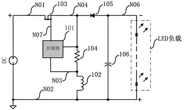
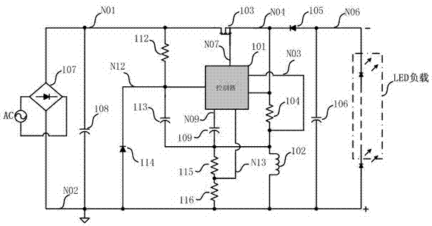
[0139] refer to image 3 , which shows the composition circuit diagram of a LED current detection and control circuit in the preferred embodiment 1 of the present invention, in figure 1 The basic circuit shown also includes a capacitor 109 , a resistor 112 , a capacitor 113 , a diode 114 , a resistor 115 and a resistor 116 .

[0140] One end of the resistor 112 is used to connect the positive pole of the DC power supply, and the other end of the resistor 112 is connected to the input end of the controller power supply 217 of the controller 101; the cathode of the diode 114 is connected to the input end of the controller power supply 217 of the controller 101 , the anode is connected to the DC power supply ground; one end of the capacitor 113 is connected to the input end of the controller power supply 217 of the controller 101, and the other end is connected to the controller ground.

[0141] The resistor 115 is connected in series with the resistor 116 and then connected in ...

no. 2 example

[0159] Such as Figure 6, the controller of the second embodiment of the LED current detection and control circuit is in figure 2 On the basis of the basic circuit of the controller shown, there are added: a protection circuit 220 , a sawtooth wave current generator 215A and a square wave generator 221 .

[0160] One output terminal of the square wave generator 221 is connected to the logic circuit 208 , and the other output terminal is connected to the sawtooth wave current generator 215A.

[0161] The sawtooth wave current generator 215A outputs a sawtooth wave current, the voltage signal generated by the sawtooth wave current on the resistor 222 is added to the source voltage signal when the switch tube 103 is turned on, and then the added voltage is sent to One of the input terminals of the first comparator 206 .

[0162] Such as Figure 5 The peripheral electrical components of the controller 101 also include: a resistor 112 , a diode 114 , a capacitor 113 , a resisto...

no. 3 example

[0168] Figure 7 It is the third embodiment of the circuit of LED current detection and control of the present invention, and figure 1 Compared with the basic circuit shown, the inductance 102 in this embodiment is the primary winding of the transformer 102A, one end of the auxiliary winding of the transformer 102A is connected to the DC power supply ground, and the other end is connected to the power input end of the controller 101 through the diode 110; The cathode of 110 is connected to the input terminal of controller power supply 217 of controller 101 .

[0169] The third embodiment of the controller:

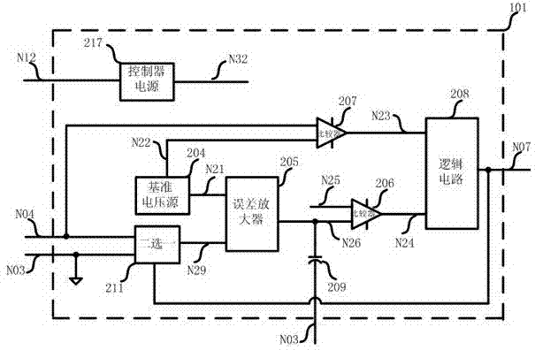
[0170] Such as Figure 8 , the controller 101 of this embodiment includes a controller power supply 217 , a reference voltage source 204 , an error amplifier 205 , a comparator 206 , a comparator 207 , a logic circuit 208 , a capacitor 209 , a switch 213 and an error amplifier 205 .

[0171] The control end of the switch 213 is connected to the output end of the logic c...


PUM


Abstract

The invention discloses a light-emitting diode (LED) current detection and control circuit and relates to the field of LED current detection and control circuits. The LED current detection and control circuit is technically characterized in that the circuit comprises a controller, a switching tube, a resistor, a diode, an inductor and a capacitor; when the switching tube is turned on, the resistor detects current which flows through the switching tube and the inductor, the current is fed to the controller, the switching tube and the inductor are prevented from being damaged because of overcurrent and the reliability of an LED driving power supply during working is improved; and when the switching tube is cut off, the resistor detects current which flows through a load LED, and since closed-loop control is adopted in the controller, the value of current output to the LED is very precise and is not influenced by input voltage, output voltage and inductance. The LED current detection and control circuit is suitable for all LED driving power supplies which adopt a BUCK-BOOST topology.

Description

technical field [0001] The invention relates to the field of LED current detection and control circuits, in particular to a LED current detection and control circuit that adopts a buck-boost topology (Buck-Boost) to output high-precision current in LED lighting. Background technique [0002] Traditional lighting technology has disadvantages such as low luminous efficiency, high power consumption, and short service life. LED lighting has the advantages of long life, energy saving, safety, and environmental protection, and is rapidly replacing traditional lighting. Unlike ordinary incandescent bulbs, LEDs can be directly connected to 220V AC mains, and require a constant output current provided by a current detection and control circuit. Current accuracy is one of the most important indicators of LED current detection and control circuits. Other indicators mainly include insulation reliability, volume size, power factor, conversion efficiency, power supply life, and electromag...

Claims


Application Information

Patent Timeline
IPC IPC(8): H05B37/02G01R19/00G01R19/175
Inventor 赵修平
Owner SHENZHEN LINGQI SEMICON CO LTD
Why Eureka
Try Eureka