
High-precision spring machine

A spring machine, high-precision technology, applied in the field of spring machines, can solve the problems affecting the spring machining accuracy, increase the difficulty of debugging, increase the difficulty of punching, etc., and achieve the effect of convenient debugging, reducing the difficulty of process realization and simple structure

Inactive Publication Date: 2012-07-04
ADTECH SHENZHEN TECH
View PDF5 Cites 0 Cited by
  • Summary
  • Abstract
  • Description
  • Claims
  • Application Information

AI Technical Summary

Problems solved by technology

[0002] Spring machine is a kind of processing machine that can make spring wire into shape. It can process springs and other parts. At present, traditional spring machines use a stepping or servo motor to drive gears and other transmission devices, and then use cams to drive multiple spring processing axes. Spring processing, in which the function of the cam is to drive the spring processing shaft to do linear reciprocating motion. The spring processing shaft and the cam are generally fixed on one side of the processing panel, and the corresponding gear transmission is installed on the other side of the panel. Generally, holes need to be drilled on the panel for The cam and the gear transmission are mechanically fixedly connected, and the installation of the spring processing shaft, cam and gear on the panel also needs to be mechanically fixed after different drilling. If the rigidity of the panel is too strong, it will increase the difficulty of drilling, but the rigidity is too weak. It will affect the spring processing; moreover, its debugging is complicated. It takes a long time to debug a spring machine according to different spring types, and because the position of each spring processing axis is fixed on the processing panel and cannot be moved, so in order to be able to process multiple shapes and Different types of springs need to be installed with many spring processing axes in different positions to form mutual cooperation, which further increases the difficulty of debugging and is prone to cumulative errors, thus affecting the processing accuracy of the springs

Method used


Image

  • High-precision spring machine
  • High-precision spring machine
  • High-precision spring machine

Examples


Embodiment 1

[0064] Embodiment 1: Take the three-axis spring machine as an example to specifically illustrate the specific implementation of the scheme:

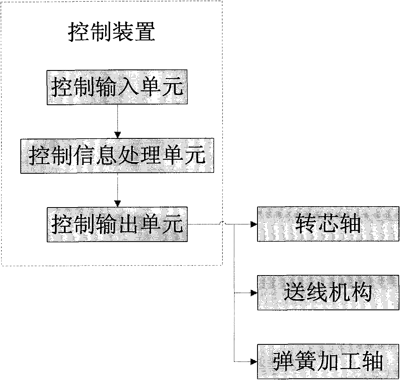
[0065] Such as Figure 4 , where each spring processing axis is converted into a different specific spring processing axis according to the different processing cutter heads. If the processing end of the axis is a top thread cutter, the spring processing axis will be converted into a top thread axis. If the spring processing axis is equipped with a tangent knife, the spring processing axis will be converted into a tangent axis;

[0066]The spring processing shaft of the three-axis spring machine is three shafts, specifically the crimping shaft, which is used to bend the spring wire rod inward during the spring processing; the top wire shaft is used to cooperate with the top wire shaft during the spring processing to make the spring The shaft that forms the desired curved shape; the tangent shaft, the shaft used to cut the formed spring ...

Embodiment 2

[0087] Taking the three-axis spring machine as an example to specifically illustrate the implementation of the improvement plan:

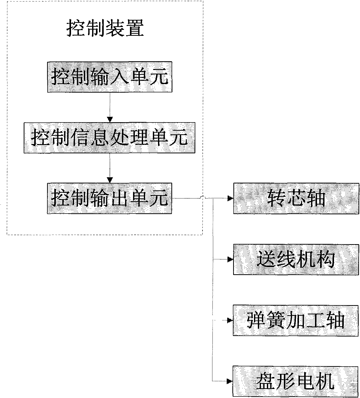
[0088] Such as Figure 5 , where each spring processing axis is converted into a different specific spring processing axis according to the different processing cutter heads. If the processing end of the axis is a top thread cutter, the spring processing axis is converted into a top thread axis. If the tool head of the spring processing axis is a tangent knife, the spring processing axis is converted into a tangent axis;

[0089] The spring processing shaft of the three-axis spring machine is three shafts, specifically the crimping shaft, which is used to bend the spring wire rod inward during the spring processing; the top wire shaft is used to cooperate with the top wire shaft during the spring processing to make the spring The shaft that forms the desired curved shape; the tangent shaft, the shaft used to cut the formed spring from the spring w...


PUM


Abstract

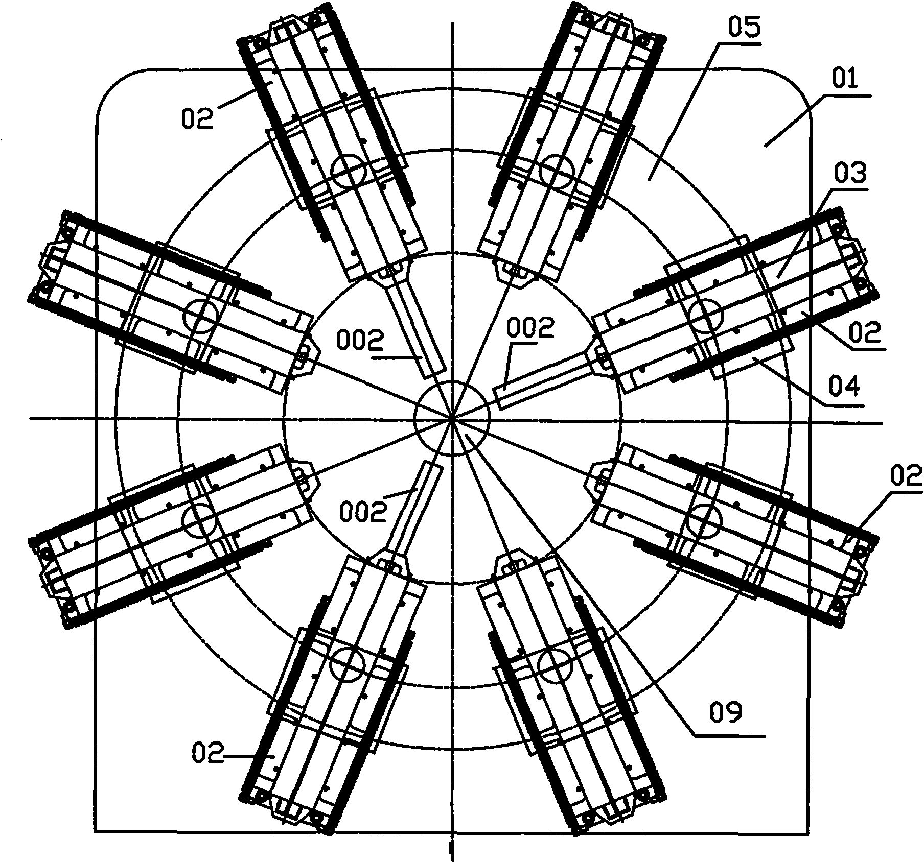
The invention relates to a high-precision spring machine, which comprises a control device, an annular sliding rail, a spring machining shaft, a rotating core shaft and a wire feeding mechanism, wherein the control device comprises a control input unit, a control information processing unit and a control output unit; the control input unit is used for inputting a control process command; the control information processing unit is used for processing and converting the input control process command into a specific control driving command, and sends the specific control driving command to the control output unit; the control output unit is used for outputting the control driving command processed by the control information processing unit; the spring machining shaft is installed on the annular sliding rail and is driven by a linear motor to ensure that the spring machining shaft carries out reciprocating motion on the processing axis to finish processing of the spring; and the linear motor, the rotating core shaft and the wire feeding mechanism are respectively electrically connected with the control output unit and are controlled to drive by the control device. The high-precision spring machine has the advantages of simple structure and high machining precision, is convenient to debug and is easy to control.

Description

technical field [0001] The invention relates to a spring machine, in particular to a high-precision spring machine whose spring processing axis is a linear motor. Background technique [0002] Spring machine is a kind of processing machine that can make spring wire into shape. It can process springs and other parts. At present, traditional spring machines use a stepping or servo motor to drive gears and other transmission devices, and then use cams to drive multiple spring processing axes. Spring processing, in which the function of the cam is to drive the spring processing shaft to do linear reciprocating motion. The spring processing shaft and the cam are generally fixed on one side of the processing panel, and the corresponding gear transmission is installed on the other side of the panel. Generally, holes need to be drilled on the panel for The cam and the gear transmission are mechanically fixedly connected, and the installation of the spring processing shaft, cam and g...

Claims


Application Information

Patent Timeline
Patent Type & Authority Applications(China)
IPC IPC(8): B21F35/00
Inventor 曾逸丁军林王晓刚
Owner ADTECH SHENZHEN TECH
Learn More