
Chip removing and cooling device for scraping roller machine and scraping roller machine

A technology of cooling device and chip conveyor, which is used in metal processing machinery parts, other manufacturing equipment/tools, maintenance and safety accessories, etc. Among the components, insufficient filtration, equipment failure and other problems, to achieve excellent filtration and cooling effects, improve filtration effect, and improve filtration accuracy

Inactive Publication Date: 2012-07-04
SHANGHAI SANY PRECISION MACHINERY
View PDF9 Cites 4 Cited by
  • Summary
  • Abstract
  • Description
  • Claims
  • Application Information

AI Technical Summary

Problems solved by technology

[0003] During the processing and production process of the existing scraping machine, the coolant mixed with iron filings and other impurities needs to be recycled. The oil tank partition and ordinary chip conveyor are mainly used to filter iron filings and other impurities, which leads to insufficient filtration. Make fine iron filings and other impurities easy to deposit in the coolant pipeline and other working parts, causing equipment failure
[0004] On the other hand, the existing scraping machine tools generally use natural cooling for the cooling liquid, and then recycle it, but relying on the natural cooling speed is relatively slow, causing the cooling liquid to be recycled again before it can be fully cooled, especially the external environment temperature When the temperature is high, the circulating coolant cannot cool down to the required temperature at all, resulting in poor cooling effect on the tool, which further affects the processing quality
It is also easy to form "oil mist" in high temperature weather, which affects the cooling effect and pollutes the environment

Method used


Image

  • Chip removing and cooling device for scraping roller machine and scraping roller machine
  • Chip removing and cooling device for scraping roller machine and scraping roller machine
  • Chip removing and cooling device for scraping roller machine and scraping roller machine

Examples


Embodiment Construction

[0042] In order to have a clearer understanding of the technical features, purposes and effects of the present invention, the specific implementation of the present invention will now be described with reference to the accompanying drawings, but it is only a preferred embodiment and is not used to limit the essential scope of the present invention.

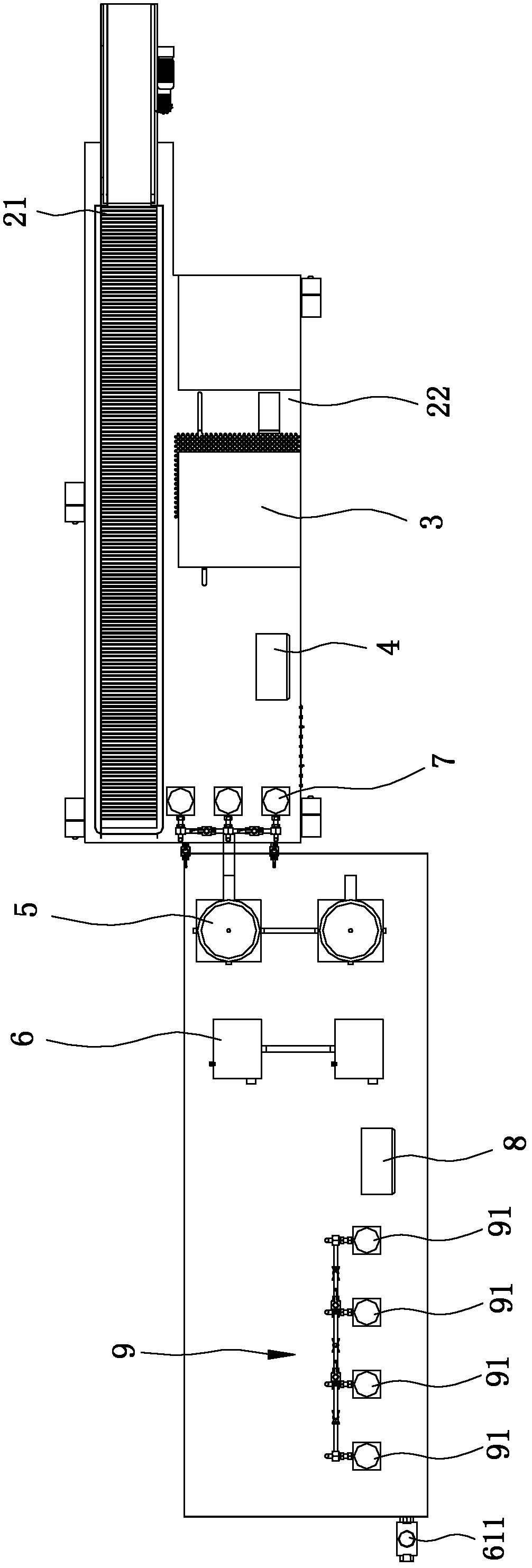
[0043] Please refer to figure 1 and figure 2 ,in figure 1 It is a front view schematic diagram of the overall structure of the chip removal cooling device of the scraping machine of the present invention, figure 2 It is a schematic plan view of the overall structure of the chip removal cooling device of the scraping machine of the present invention, as shown in the figure, the chip removal cooling device of the present invention mainly includes: a base frame 1; a chip removal unit 2, which is arranged on the base frame 1 and discharges Chip unit 2 receives the mixture of iron filings and coolant generated when the scraping mac...


PUM


Abstract

The invention discloses a chip removing and cooling device for a scraping roller machine and a scraping roller machine. The chip removing and cooling device for the scraping roller machine comprises a pedestal, a chip removing unit, a toothed magnetic separator, a first control unit, a filter, a refrigerator, a back oil box and a second control unit, wherein the chip removing unit is arranged on the pedestal and is used for receiving a mixture of scrap iron generated by the scraping roller machine and a coolant, and preliminarily filtering the scrap iron with larger volume, and the toothed magnetic separator is arranged on the pedestal and is used for receiving the coolant preliminarily filtered by the chip removing unit and filtering thin scrap iron; the first control unit is connected with and control the chip removing unit and the toothed magnetic separator, and the filter is arranged on the pedestal and is used for receiving the coolant filtered by the toothed magnetic separator and precisely filtering the coolant; the refrigerator is arranged on the pedestal and is used for receiving and cooling the filtered coolant; and the back oil box is arranged on the pedestal and is used for receiving and collecting the coolant output by the refrigerator, and the second control unit is connected with and controls the refrigerator. The chip removing and cooling device for the scraping roller machine and the scraping roller machine can improve the filter precision of the coolant and effectively reduce the temperature of the coolant.

Description

technical field [0001] The invention relates to a chip removal cooling device, in particular to a scraper cooling device and a scraper. Background technique [0002] With the rapid development of the global construction machinery industry, the demand for oil cylinders and other products continues to increase. Traditional processing and production methods such as girder grinding can no longer meet the requirements of manufacturers for production efficiency. The barrel is processed, including rough boring, scraping, tumbling and other processes, to achieve one-time processing, and the processing efficiency can reach more than ten times that of the traditional beam grinding process. Therefore, it has become more and more favored by manufacturers and gradually popularized and applied. In the next few years, it will replace the traditional girder grinding process and become the main way of cylinder barrel processing. [0003] During the processing and production process of the e...

Claims


Application Information

Patent Timeline
Patent Type & Authority Applications(China)
IPC IPC(8): B23Q11/12B23Q11/00B23P23/00
Inventor 王永兴张金涛
Owner SHANGHAI SANY PRECISION MACHINERY
Learn More