Leg of multi-legged walking robot

A walking robot and robot foot technology, applied in the field of robotics, can solve problems such as limiting the range of movement of robot feet, complex structure of flat-bottomed feet, and tripping, and achieve the goals of improving measurement range and accuracy, flexible and reliable walking, and reducing costs Effect

Inactive Publication Date: 2012-07-04
ZHEJIANG UNIV
7 Cites 21 Cited by

AI-Extracted Technical Summary

Problems solved by technology

First, the structure of the flat-bottomed foot is complex, while the structure of the spherical-bottomed foot is simple and compact; secondly, the passive joints in ...

Method used

[0022] The multi-leg walking robot foot dynamometer is composed of a pressure sensor 13 and a signal acquisition processor 14. The pressure sensor 13 is arranged on the lower end circular boss of the foot connector 6, and the signal line of the pressure sensor 13 is connected with the signal acquisition processor 14 through the wire groove 15 at the lower end of the foot connector 6, and the force signal measured by the pressure sensor 13 is Signal acquisition and signal processing are performed by the signal acquisition processor 14, and reliable and eff...

Abstract

The invention discloses a leg of a multi-legged walking robot. The existing flat soled leg structure is complex and easy to cause tripping over. The robot leg comprises a leg mechanical device of the multi-legged walking robot and a leg dynamometrical device of the multi-legged walking robot. The leg mechanical device of the multi-legged walking robot comprises a spherical foot, a damping dynamometrical portion and a shank connector, and the damping dynamometrical portion comprises a spherical foot connector, a leg connector, a leg sleeve, a damping compression spring, a pressure pad and fixing screws. The leg dynamometrical device of the multi-legged walking robot consists of a pressure sensor and a signal acquisition processor. The leg of a multi-legged walking robot is in the sphericalfoot end type foot structure and simple and compact in structure, and the multi-legged walking robot is flexible and reliable in walking. Impact between the multi-legged walking robot and the ground during walking of the robot is effectively reduced by means of the compression spring damping device. Difficulty and complexity in dynamometry of the leg of the multi-legged walking robot are greatly reduced by using the pressure sensor for dynamometry of the leg of the multi-legged walking robot.

Application Domain

Technology Topic

Image

  • Leg of multi-legged walking robot
  • Leg of multi-legged walking robot
  • Leg of multi-legged walking robot

Examples

  • Experimental program(1)

Example Embodiment

[0019] The present invention will be further described below in conjunction with the drawings.
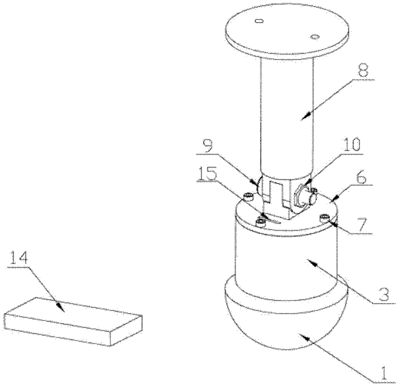
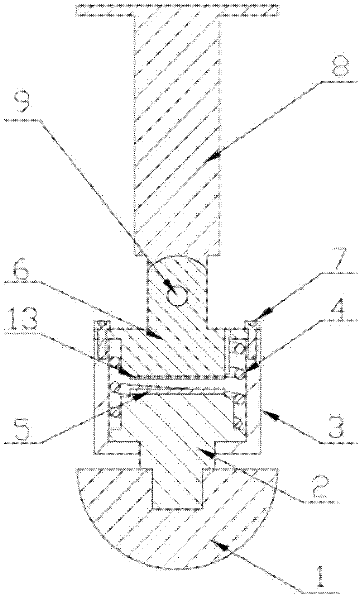
[0020] Such as figure 1 , figure 2 As shown, the present invention adopts a spherical foot-end foot structure, which is composed of a multi-pedal walking robot foot mechanical device and a multi-pedal walking robot foot force measuring device.
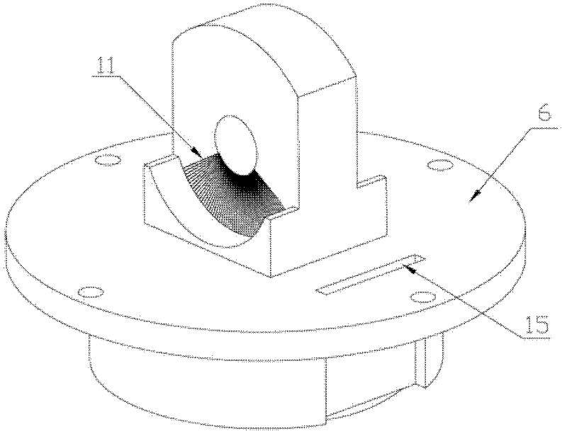
[0021] The foot mechanism of the multi-leg walking robot comprises a spherical foot end 1, a shock-absorbing force measuring part and a calf-foot connecting piece 8. The spherical foot end 1 is made of rubber material. This foot end is in flexible contact with the ground after landing, which can increase the friction between the feet of the multi-legged robot and the ground to prevent the multi-legged robot from falling When walking, slipping can form a buffer with the ground to reduce impact, which can effectively improve the adaptability of the multi-legged walking robot to the environment. The shock-absorbing force measurement part is composed of a spherical foot end connector 2, a foot sleeve 3, a shock-absorbing compression spring 4, a pressure pad 5, a foot connector 6, and a fixing screw 7. The upper end of the spherical foot end connector 2 is placed in the foot sleeve 3. The step ring of the spherical foot end connector 2 and the inner wall of the foot sleeve 3 are in clearance fit. The step ring of the spherical foot end connector 2 and the foot The inner walls of the sleeve 3 can slide relatively, and a pressure pad 5 is placed on the circular boss of the spherical foot end connector 2. The circular boss is located in the foot sleeve 3, and the lower end of the spherical foot end connector 2 penetrates After passing through the round hole of the foot sleeve 3, it is threadedly connected with the spherical foot end 1; the lower end of the foot connecting piece 6 is fixedly connected with the foot sleeve 3 by a fixing screw 7; the shock-absorbing compression spring 4 is placed in the foot sleeve 3 , And sleeved on the upper end of the spherical foot end connector 2 and the lower end of the foot connector 6 at the same time, the spring force generated by the shock-absorbing compression spring 4 acts on the step ring of the spherical foot end connector 2 and the foot connector 6 to make The bottom surface of the step ring of the spherical foot end connector 2 is in contact with the inner bottom surface of the foot sleeve 3, and the shock-absorbing compression spring 4 forms a certain gap between the lower end of the foot connector 6 and the upper end of the spherical foot end connector 2. The upper end of the foot connector 6 and the fork head of the calf foot connector 8 are fixed by a fixing bolt 9 and a fixing nut 10. The upper end of the foot connector 6 and the fork head of the calf foot connector 8 can be rotated around the fixing bolt 9 A certain angle, which has the function of the ankle joint, such as image 3 The upper end side plane of the foot connector 6 is shown with an angular scale 11 of 0 to 120 degrees, and the angular scale 11 is separated by 1 degree, such as Figure 4 A notch 12 is opened on the prong of the calf-foot connecting piece 8 shown. The notch 12 on the prong of the calf-foot connecting piece 8 and the angle engraved line 11 on the upper end side of the foot connecting piece 6 can be used to measure the foot connecting piece 6 relative to The angle that the calf-foot connecting piece 8 has turned, and when the angle of the foot connecting piece 6 relative to the calf-foot connecting piece 8 reaches the desired angle, tighten the fixing bolt 9 and the fixing nut 10 to make the foot connecting piece 6 relative to the calf The position of the connecting piece 8 is fixed.
[0022] The foot force measuring device of the multi-leg walking robot is composed of a pressure sensor 13 and a signal acquisition processor 14. The pressure sensor 13 is arranged on the circular boss at the lower end of the foot connector 6. The signal line of the pressure sensor 13 is connected to the signal acquisition processor 14 through the wire groove 15 at the lower end of the foot connector 6. The force signal measured by the pressure sensor 13 The signal acquisition processor 14 performs signal acquisition and signal processing, and the signal acquisition processor 14 obtains reliable and effective force signal measurement values. The size of the upper surface of the pressure pad 5 on the circular boss of the spherical foot end connector 2 is the same as the effective measurement area of ​​the pressure sensor 13, and the force received by the foot each time acts evenly on the pressure sensor 13 through the pressure pad 5. The measurement accuracy of the pressure sensor 13 is greatly improved, so that the force on the feet of the multi-legged walking robot can be accurately measured.
[0023] The working process of the foot of the multi-leg walking robot will be described in detail below.
[0024] Before controlling the walking of the multi-legged robot, firstly loosen the fixing bolt 9 and the fixed nut 10 of the multi-legged robot foot. According to the walking gait of the multi-legged robot, manually adjust the angle of the multi-legged robot foot relative to the calf. Measure the angle of the multi-pedal walking robot's foot relative to the lower leg through the angle engraved line 11 in the foot connector 6 and the notch 12 on the fork head of the calf foot connector 8. After the required angle is adjusted, the fixing bolt 9 and the fixing nut 10 Tightening makes the position of the foot connecting piece 6 relative to the calf-foot connecting piece 8 fixed. Then the multi-legged walking robot can walk. When the feet of the multi-pedal walking robot are in contact with the ground, the spherical foot end 1 made of rubber material produces a slight deformation. The spherical foot end 1 and the ground are in flexible contact with the ground force. The lower spherical foot end connector 2 connected with the spherical foot end 1 slides in the foot sleeve 3 while compressing the shock-absorbing compression spring 4. The shock-absorbing compression spring 4 buffers and reduces the shock of the multi-leg walking robot. The shock-absorbing compression spring 4 It is further compressed until the pressure pad 5 contacts the pressure sensor 13. The pressure pad 5 squeezes the pressure sensor 13 under the action of the ground force. The pressure sensor 13 measures the squeezing force received and inputs the measured force signal to In the signal acquisition processor 14, reliable and effective force information can be obtained through the acquisition and processing of the force signal by the signal acquisition processor 14. In the walking process of the multi-legged walking robot, the force of the ground on the feet of the multi-legged walking robot can be measured in real time. The measured force information is both accurate and rapid, and can well grasp the multi-legged walking robot's walking process. Stress situation. The force information obtained can be used to comprehensively analyze the force exerted by the multi-legged walking robot during walking, and the analysis results can guide the control of the multi-legged walking robot.

PUM

no PUM

Description & Claims & Application Information

We can also present the details of the Description, Claims and Application information to help users get a comprehensive understanding of the technical details of the patent, such as background art, summary of invention, brief description of drawings, description of embodiments, and other original content. On the other hand, users can also determine the specific scope of protection of the technology through the list of claims; as well as understand the changes in the life cycle of the technology with the presentation of the patent timeline. Login to view more.

Similar technology patents

Classification and recommendation of technical efficacy words

Why Eureka
Try Eureka