On-site crane car for power transformation engineering

A crane truck and on-site technology, applied to cranes and other directions, can solve problems such as hidden dangers of accidents, inability to use lifting equipment, and reduced power transmission and transformation efficiency

Inactive Publication Date: 2012-07-04
STATE GRID CORP OF CHINA +1
View PDF6 Cites 19 Cited by
  • Summary
  • Abstract
  • Description
  • Claims
  • Application Information

AI Technical Summary

Problems solved by technology

Due to the large size of the crane, it is used in the live equipment area. The swing and lifting of the boom are limited by the site space and the surrounding live equipment. The operation is very inconvenient and there are serious accident hazards. Sometimes the power outage area has to be expanded to meet the Conditions of Use
For example, when replacing a 110kV outdoor current transformer, the current transformer is generally located behind the switch, and the crane is on the road. The lifting arm must pass the switch to lift the transformer. Restricted by the switch; for another example, when replacing the 110kV bus PT, its installation position or the crane cannot reach it, or the lifting height is affected by the live bus above; another example is to replace or install the outdoor 110kV A (side) switch, 35kV outdoor switch, In the 110kV line PT and other operations, there are cases where the lifting equipment is limited by the site conditions and the power outage scope is expanded, and even the lifting equipment cannot be used.
If a forklift is used, there are problems such as insufficient lifting height, heavy dead weight, and inconvenient transportation.
This type of operation is very common in power substation maintenance or installation and expansion projects, which greatly affects the long construction period of the project, and often results in large-scale and long-term power outages, reduced power transmission and transformation efficiency, and low operating safety factors. At present, this problem has not been solved satisfactorily.

Method used


Image

  • On-site crane car for power transformation engineering
  • On-site crane car for power transformation engineering
  • On-site crane car for power transformation engineering

Examples


Embodiment Construction

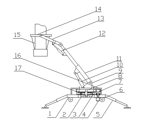
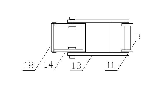
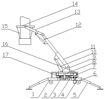
[0018] See figure 1 , figure 2 , The crane truck for substation engineering site of the present invention has a base 1 on which a rotating mechanism is provided. The rotating mechanism is composed of a lower fixed seat 2, an upper fixed seat 3, a lower turntable 17 and an upper turntable 8. , The lower fixing base 2 and the upper fixing base 3 are respectively fixedly mounted on the base 1 through fastening connectors. The lower turntable 17 is located between the lower fixing seat 2 and the upper fixing seat 3, and is respectively connected to the lower fixing seat 2 and the upper fixing seat 3 through ball and ball raceways or rolling grooves, and the upper turntable 8 passes through the upper fixing seat through the central axis 3 is fixedly connected with the lower turntable 17, so that the lower turntable 17 and the upper turntable 8 can rotate freely and lightly, so that the lifting boom 11 can rotate flexibly. The upper turntable 8 is provided with an outer ring gear, ...


PUM


Abstract

The invention discloses an on-site crane car for power transformation engineering, which comprises a base, a lifting and hanging rod mounted on the base through a rotating mechanism, an elevation angle regulating mechanism arranged at the lower part of the lifting and hanging rod, and a suspension rope hanging adapter arranged at the top end of the lifting and hanging rod through a forcipated support, wherein the lifting and hanging rod is connected with the rotating mechanism through a hinged support and the base is provided with travel wheels. The crane car is particularly suitable for on-site uninstallation and installation of equipment in power transformation engineering. The crane car has a small size and a light weight, occupies less space, better solves the problem that the large-size lifting device can not be used in a transformer station in certain cases, eliminates the limitation of on-site spatial position and peripheral electrified equipment on lifting operation, and can greatly reduce the labor intensity of operating staff, reduce the power failure range during the equipment lifting process and increase the operating efficiency and the operation safety coefficient. Besides, the crane car has the advantages of being convenient for folding, transport and storage, easy to operate and convenient to use.

Description

[0001] Technical field [0002] The invention belongs to the technical field of power system installation and maintenance equipment, and particularly relates to a crane truck on site for power transformation projects. Background technique [0003] In power station expansion or renovation projects, large cranes are usually used for lifting equipment. Due to the large size of the crane, it is used in the live equipment area, and the swing and lifting of its boom is limited by the location of the site and the surrounding live equipment. The operation is very inconvenient and there are serious accident risks. Sometimes the power outage area has to be expanded to meet Conditions of Use. For example, when replacing a 110kV outdoor current transformer, the current transformer is generally located behind the switch, and the crane station is on the road. The boom must pass the switch to lift the transformer. The lifting height of the boom is affected by the upper line, and the swing angle...

Claims


Application Information

Patent Timeline
Patent Type & Authority Applications(China)
IPC IPC(8): B66C23/06B66C23/84
Inventor 秦卫东郭跃东苏长宝
Owner STATE GRID CORP OF CHINA
Why Eureka
Try Eureka