Energy-saving lime kiln

A technology of lime kiln and kiln body is applied in the field of material calcining device, which can solve the problems of wasting heat energy, unutilized flue gas, low preheating temperature and increasing fuel consumption, etc., and achieves the effect of reducing cost, calcining thoroughly and improving quality.

Active Publication Date: 2012-07-04
浙江天石纳米科技股份有限公司
View PDF5 Cites 15 Cited by
  • Summary
  • Abstract
  • Description
  • Claims
  • Application Information

AI Technical Summary

Problems solved by technology

[0004] The present invention overcomes the disadvantages that the flue gas discharged from the existing lime kiln is not utilized and heat energy is wasted, and the low preheating temperature of the combustion-supporting air in the lime kiln increases the fu

Method used


Image

  • Energy-saving lime kiln
  • Energy-saving lime kiln
  • Energy-saving lime kiln

Examples


Embodiment 1

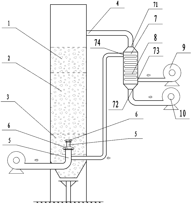
[0021] Embodiment 1: a kind of energy-saving lime kiln (see attached figure 1 ), including the vertical kiln body, the kiln body is preheating zone 1, calcining zone 2, and cooling zone 3 from top to bottom. A kiln gas discharge pipe 4 is arranged above the preheating zone. The kiln gas discharge pipe is used to discharge the flue gas in the kiln body. The temperature of the discharged flue gas is generally between 250°C and 300°C. The kiln gas discharge pipe is connected to the air inlet 71 of the heat exchanger 7, and the high-temperature flue gas discharged from the kiln body is transported into the heat exchanger through the air inlet. The blower 9 is connected, and the air outlet 72 of the heat exchanger is connected with the exhaust fan 10 . The blower blows the air at normal temperature into the heat exchange tube, and after heat exchange between the high temperature flue gas and the normal temperature air in the heat exchange tube, the flue gas is extracted by the exh...

Embodiment 2

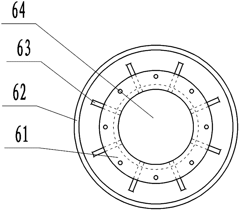
[0023] Embodiment 2: a kind of energy-saving lime kiln (see attached figure 1 ), its structure is similar to Example 1. The main difference lies in the structure of the hood 6 . Wind cap 6 comprises cap seat 61, cap tube 66 and cap 62 (see attached Figure 4 , attached Figure 5 ), the cap seat is cylindrical, and the cap seat is provided with a ventilation hole 64 adapted to the air duct 5, the end of the ventilation hole of the upper hood is closed, and the end of the ventilation hole of the lower hood is provided with a preheating air input device The through hole that the air duct fits into, and the air duct passes through the through hole. The lower end of the cap seat is provided with an outward flange, and a countersunk through hole is provided on the flange. The upper end of the air duct is provided with an outward flange, and the flange is provided with a through hole adapted to the through hole of the countersunk head. The two flanges are fitted together and conn...


PUM


Abstract

The invention discloses an energy-saving lime kiln, which aims to solve the problems that heat energy is wasted because smoke discharged by the conventional lime kiln is not utilized and fuel consumption is increased because the preheating temperature of combustion-supporting air of the lime kiln is low. The energy-saving lime kiln comprises a kiln body, wherein a preheating zone, a calcining zone and a cooling zone are sequentially on the kiln body from top to bottom; a kiln gas outlet pipe is arranged above the preheating zone; a normal-temperature air input device and a preheated air inputdevice fixed on the normal-temperature air input device are arranged in the cooling zone; each of the normal-temperature air input device and the preheated air input device comprises an air pipe and an air cap connected with an air outlet of the air pipe; the air cap of the preheated air input device is arranged above the air cap of the normal-temperature air input device; the two air caps form adouble-layer air cap structure; the kiln gas outlet pipe is connected with an air inlet of a heat exchanger; a heat exchange pipe is arranged in the heat exchanger; a cold air inlet of the heat exchange pipe is connected with an air blower; a hot air outlet of the heat exchange pipe is connected with the air pipe of the preheated air input device; and an air outlet of the heat exchanger is connected with a draft fan.

Description

technical field [0001] The invention relates to a material calcining device, in particular to a high-efficiency and energy-saving lime kiln for calcining lime. Background technique [0002] At present, the flue gas of most lime kilns is directly discharged, and the average temperature of the discharged flue gas is between 250°C and 300°C. The high-temperature flue gas is directly discharged to waste the heat. As the combustion aid of the lime kiln, air is continuously fed into the lime kiln. The combustion temperature in the lime kiln is very high, generally around 1100°C, and the air combustion aid will also reach a very high temperature when it supports combustion. At present, the commonly used method is to feed normal temperature air into the cooling zone of the lime kiln. The normal temperature air cools the lime in the cooling zone first, and at the same time preheats itself. The preheated air is used as combustion air, but these preheated air The temperature is ...

Claims


Application Information

Patent Timeline
IPC IPC(8): C04B2/10C04B2/12
CPCY02P40/40
Inventor 方笑霞
Owner 浙江天石纳米科技股份有限公司
Why Eureka
Try Eureka