Chemical mechanical polishing size
A polishing slurry and oxidant technology, applied in other chemical processes, chemical instruments and methods, polishing compositions containing abrasives, etc., can solve the problems of insufficient polishing speed, residual, and overall corrosion static corrosion rate, etc., to reduce static The effect of corrosion rate
Active Publication Date: 2015-05-27
ANJI MICROELECTRONICS TECH (SHANGHAI) CO LTD
View PDF13 Cites 0 Cited by
- Summary
- Abstract
- Description
- Claims
- Application Information
AI Technical Summary
Problems solved by technology
However, the above-mentioned polishing slurry for copper has insufficient polishing speed, and there are defects, scratches, stains and copper residues on the substrate surface after use, or the depression of the copper block after polishing is too large, or there are defects in the polishing process. Problems such as local or overall corrosion and high static corrosion rate of copper at room temperature and polishing temperature (such as 50°C)
Method used
View moreImage
Smart ImageViewing Examples
Examples
Embodiment 1~47
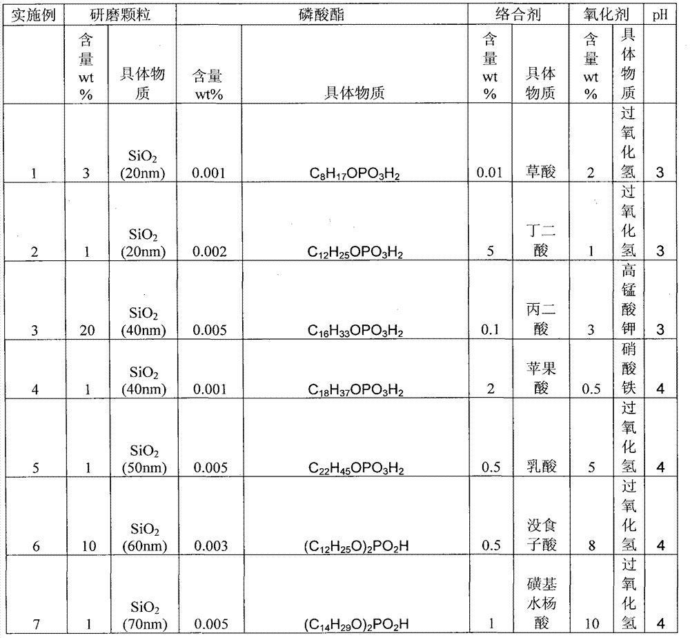
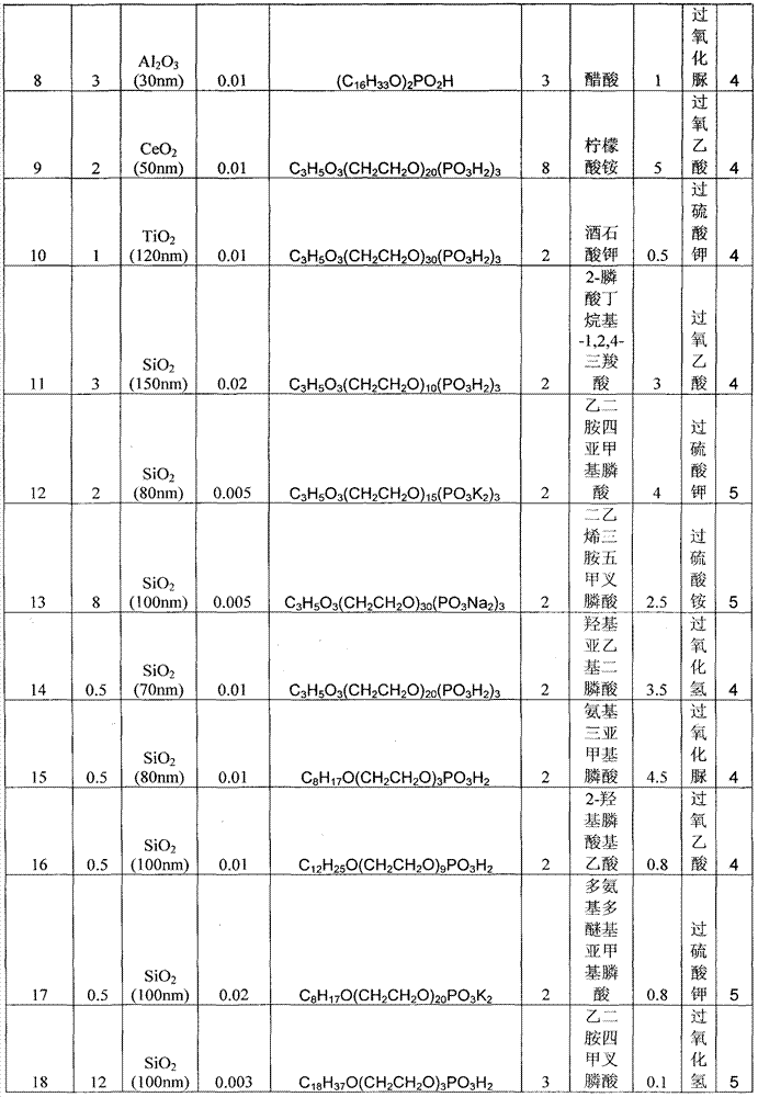
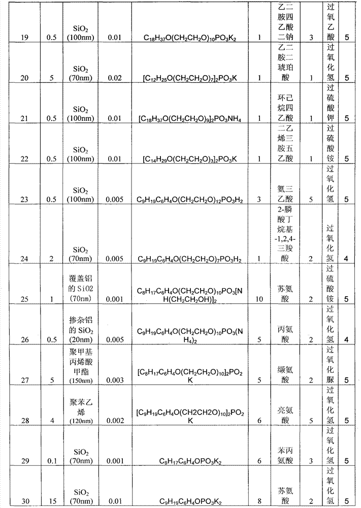
[0021] Table 1 shows Examples 1-47 of the chemical mechanical polishing solution of the present invention. According to the formula given in the table, the other components except the oxidizing agent are mixed evenly, and the mass percentage is made up to 100% with water. with KOH or HNO 3 Adjust to desired pH. Add oxidant before use and mix evenly.
[0022] Table 1 Examples 1-47
[0023]
[0024]
[0025]
[0026]
[0027]
Login to View More PUM
| Property | Measurement | Unit |
|---|---|---|
| particle diameter | aaaaa | aaaaa |
Abstract
A chemical mechanical polishing slurry for use in copper, comprising at least a phosphate ester surfactant as well as grinding particles, a complexing agent and an oxidizing agent. Using the slurry in the present invention can decrease the static erosion rate of copper, suppress the removing rate of copper at low pressures and reduce the disc-shaped depressions after polishing.
Description
technical field [0001] The present invention relates to a chemical mechanical polishing slurry for copper. Background technique [0002] With the development of microelectronics technology, the integration of very large scale integrated circuit chips has reached billions of components, and the feature size has entered the nanometer level, which requires hundreds of processes in the microelectronics process, especially multi-layer wiring, Substrates and media must undergo chemical mechanical planarization. VLSI wiring is being transformed from traditional Al to Cu. Compared with Al, Cu wiring has low resistivity, high electromigration resistance, and short RC delay time. The advantages of Cu wiring have made it replace Al as an interconnect metal in semiconductor manufacturing. However, there is no known technology for effectively plasma etching or wet etching copper material to fully form copper interconnections in integrated circuits, so chemical mechanical polishing of c...
Claims
Login to View More Application Information
Patent Timeline
 Patent Type & Authority Patents(China)
IPC IPC(8): C09G1/02
CPCC09G1/02C09K3/1463H01L21/3212
Inventor 荆建芬蔡鑫元张建
Owner ANJI MICROELECTRONICS TECH (SHANGHAI) CO LTD
Features
- R&D
- Intellectual Property
- Life Sciences
- Materials
- Tech Scout
- Unparalleled Data Quality
- Higher Quality Content
- 60% Fewer Hallucinations
Learn More Browse by: Latest US Patents, China's latest patents, Technical Efficacy Thesaurus, Application Domain, Technology Topic, Popular Technical Reports.
© 2025 PatSnap. All rights reserved.Legal|Privacy policy|Modern Slavery Act Transparency Statement|Sitemap|About US| Contact US: help@patsnap.com


