Steel projection material
A shot peening and quality technology, applied in the field of iron and steel projection materials, can solve the problems of large deviations in metal structure and hardness, rapid consumption of projection materials, uneven completion of shot peening surfaces, etc., to improve hardenability and tempering hardness. Effect
- Summary
- Abstract
- Description
- Claims
- Application Information
AI Technical Summary
Problems solved by technology
Method used
Image
Examples
Embodiment 1
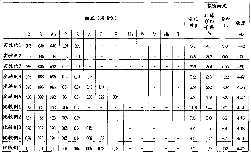
[0028] In Examples 1 to 3, the chemical composition of the first aspect of the present invention was adjusted so that P and S were 0.04 to 0.05%, and the effects of C, Si, and Mn were investigated in particular. Example 1 is a composition in which C, Si, and Mn are close to the lower limit, Example 2 is a composition in which C, Si, and Mn are close to the upper limit, and Example 3 is the most common composition. The porosity, non-spherical particle ratio, and lifetime ratio of the samples of Examples 1 to 3 are not much different.
[0029] In contrast, in Comparative Example 1 in which C, Si, and Mn were lower than the composition lower limit of the first embodiment of the present invention, the porosity and non-spherical particle ratio increased, but the lifetime ratio decreased significantly. This is because the deoxidation effect at the time of melting is insufficient because C, Si, and Mn are low, and defects such as voids increase. In addition, in comparison 2 in which...
Embodiment 4
[0030] In Example 4, the influence of Al was investigated. As a result, when Al was contained in the range of 0.04 to 0.12% by mass, the porosity and non-spherical particle ratio were significantly reduced, and the lifetime ratio was also improved. This is considered to be due to the deoxidizing effect of Al.
[0031] In contrast, in Comparative Example 3 in which Al exceeded the upper limit of the range of 0.04 to 0.12% by mass %, although the porosity was low, the non-spherical particle ratio increased and the lifetime ratio also decreased. This is considered to be due to the increase of oxides formed on the surface of the melt in the case of excess Al, thereby suppressing the surface tension and degrading the shape.
Embodiment 5
[0032] In Example 5, the influence of Cr was investigated. As a result, the porosity and non-spherical The particle rate was significantly reduced, and the lifetime ratio was also increased, giving excellent results.
[0033] On the other hand, in Comparative Example 4 in which Cr exceeded the upper limit of the range of 0.1 to 1.2% by mass %, the non-spherical particle ratio increased compared with Example 5, and the lifetime ratio decreased. It is presumed that when Cr is excessive, oxides formed on the surface of the melt increase to deteriorate the shape as in the case of Al, and at the same time, carbides of Cr tend to be formed, thereby reducing toughness.
PUM
| Property | Measurement | Unit |
|---|---|---|
| Hardness | aaaaa | aaaaa |
Abstract
Description
Claims
Application Information
 - R&D
- Intellectual Property
- Life Sciences
- Materials
- Tech Scout
- Unparalleled Data Quality
- Higher Quality Content
- 60% Fewer Hallucinations
Browse by: Latest US Patents, China's latest patents, Technical Efficacy Thesaurus, Application Domain, Technology Topic, Popular Technical Reports.
© 2025 PatSnap. All rights reserved.Legal|Privacy policy|Modern Slavery Act Transparency Statement|Sitemap|About US| Contact US: help@patsnap.com


