Double-plate or double-side film coating system

A double-sided coating and coating chamber technology, applied in sputtering coating, ion implantation coating, vacuum evaporation coating, etc., can solve the problems of low production efficiency, reduced glass cleaning results, and high equipment maintenance costs in the glass coating production line. Achieve the effect of saving human resource loss, facilitating equipment maintenance, and long maintenance intervals

Active Publication Date: 2012-07-04
广东腾胜科技创新有限公司
View PDF5 Cites 28 Cited by
  • Summary
  • Abstract
  • Description
  • Claims
  • Application Information

AI Technical Summary

Problems solved by technology

[0002] In the current commonly used glass coating production line, the surface coating process of glass is generally in the form of single-piece coating, and its production efficiency is quite low.
At the same time, when the workpiece is small, the entire coating process of the workpiece is generally completed in the same vacuum chamber, which makes the internal structure of the vacuum chamber complex and the equipment maintenance cost is also quite high; when the production line is used for processing larger workpieces, since there is no dedicated Conveying equipment, after the glass is cleaned, is usually transported into the workpiece frame by manual transportation, and then the workpiece frame is sent into the vacuum chamber through the transmission roller, which makes the production efficiency of the glass coating production line low, the labor intensity of the workers is high, and the investment in human resources is also high. , at the same time, during the conveying process of this method, the glass is easily contaminated, which reduces the cleaning result of the glass in the pre-order cleaning machine and affects the product quality
At present, manipulators are also used for transportation, but its structure is complex and the production cost is quite high

Method used


Image

  • Double-plate or double-side film coating system
  • Double-plate or double-side film coating system
  • Double-plate or double-side film coating system

Examples


Embodiment 1

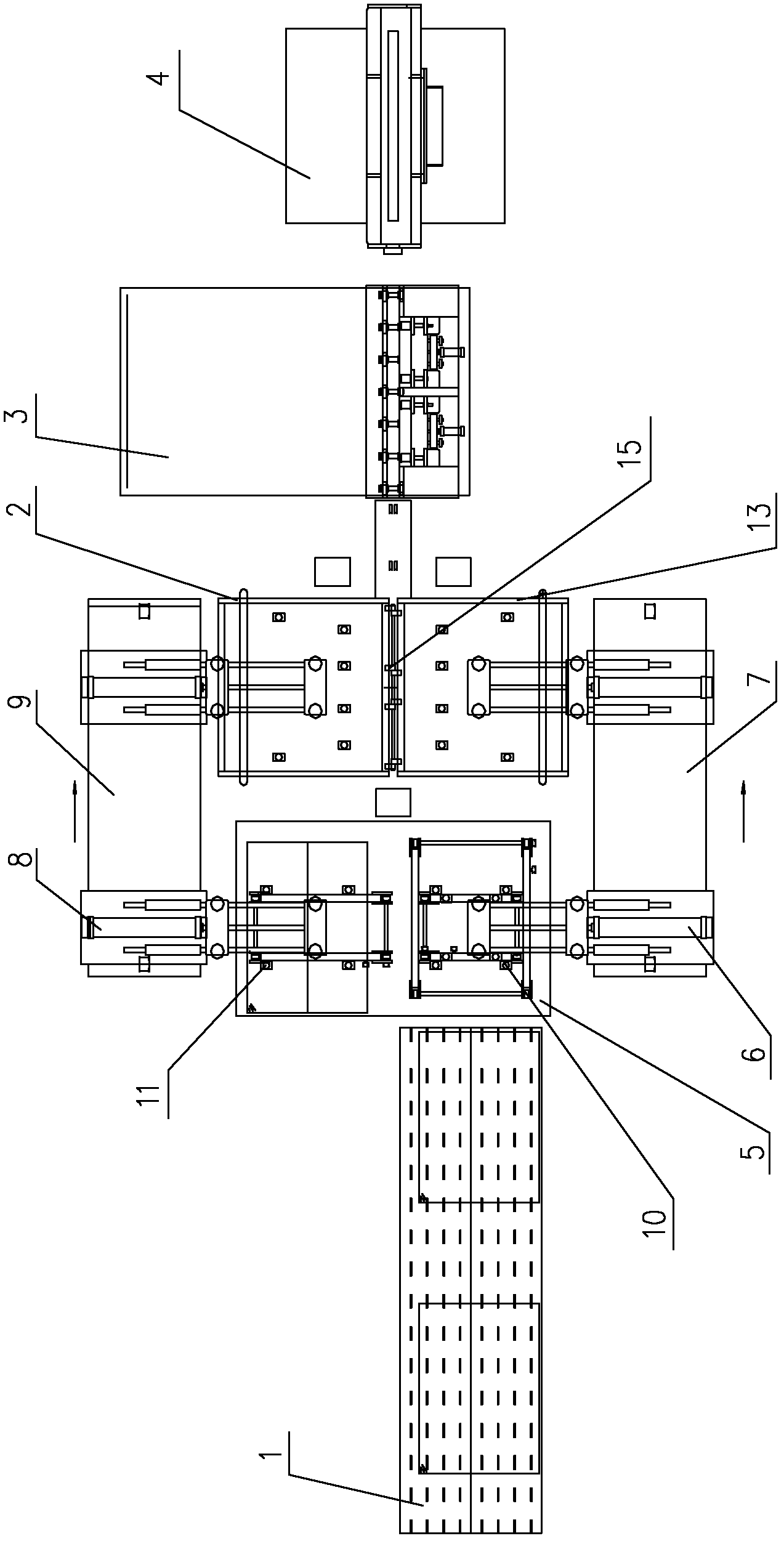
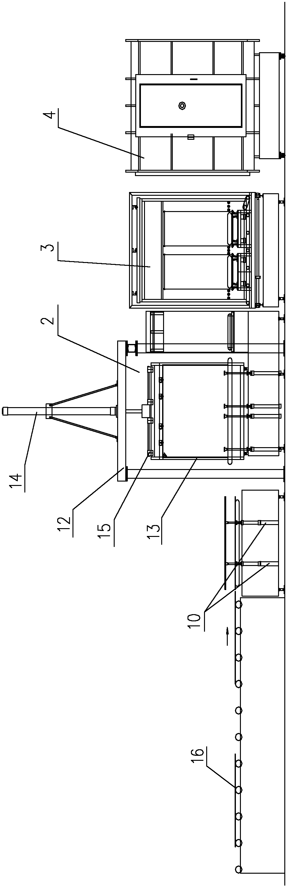
[0040] In this embodiment, a double-chip or double-sided coating system has a structure such as Figure 5 or Figure 6 As shown, it includes a plurality of vacuum chambers arranged in a straight line, and a through hole is provided between any adjacent two vacuum chambers. The first vacuum chamber is the film feeding chamber 4, and the last vacuum chamber is the film output chamber 23. At least one coating chamber 20 is arranged between the film feeding chamber 4 and the film discharging chamber 23; the chamber walls of the coating chambers located on the left and right sides of the workpiece conveying direction are provided with chamber doors, and magnetron sputtering targets 32 are installed on each chamber door.

[0041] A film feed frame 3 is provided outside the film feed port of the film feed chamber 4 , and a film discharge rack 24 is provided outside the film discharge port of the film discharge chamber 13 .

[0042] A plurality of vacuum chambers also includes a pre-...

Embodiment 2

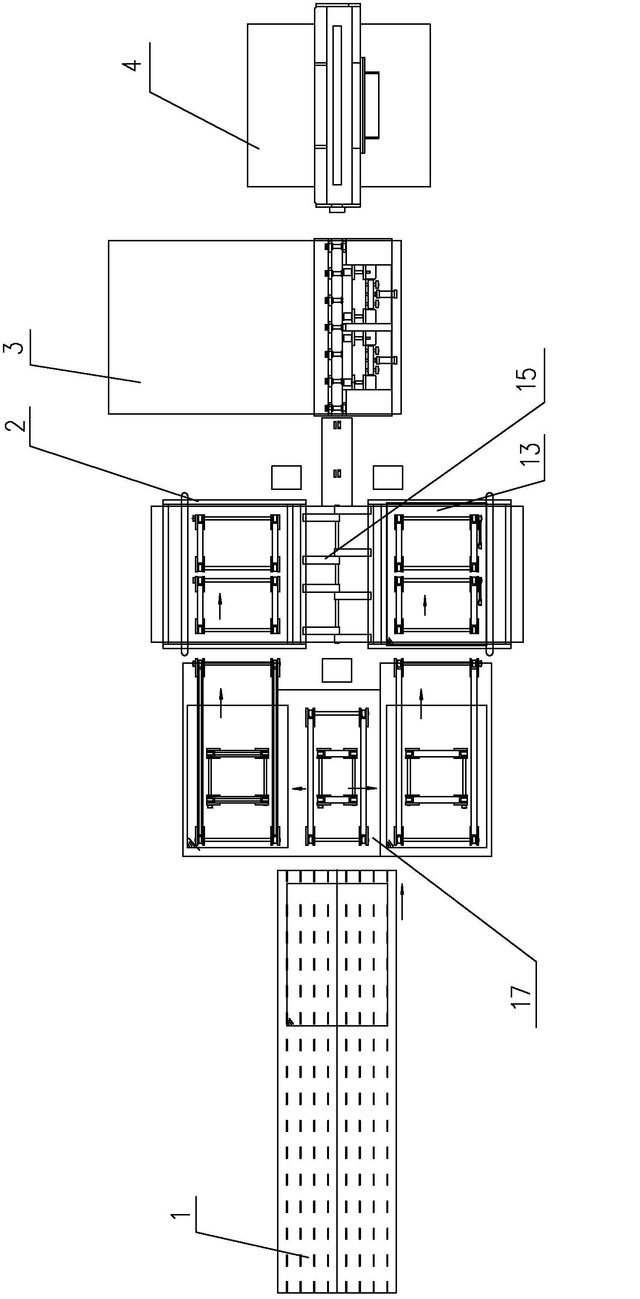
[0056] A kind of double-sheet or double-sided coating system of this embodiment, compared with embodiment 1, its difference lies in the structural form of its double-sheet conveying mechanism, as image 3 or Figure 4 As shown, the double-sheet transmission mechanism includes a reciprocating conveyor belt 17 that moves back and forth on the side of the hinge frame. The reciprocating conveyor belt 17 is arranged at the output end of the washing machine conveyor table 1. hinge frame 2;

[0057] There are 3 workpiece positions on the reciprocating conveyor belt 17, including the middle workpiece position and 2 side workpiece positions. The middle workpiece position is correspondingly set at the output end of the conveyor table of the washing machine, and the 2 side workpiece positions are respectively arranged on both sides of the middle workpiece position. .

[0058]When the double-piece workpiece input device is used, the working process of the double-piece conveying mechanis...

Embodiment 3

[0060] This embodiment is a double-sheet or double-sided coating system. Compared with Embodiment 1, its difference lies in the structure of each vacuum lock, the first vacuum lock, the second vacuum lock, the third vacuum lock, and the fourth vacuum lock , the fifth vacuum lock, the sixth vacuum lock and the seventh vacuum lock have the same structure, such as Figure 8 As shown, it includes a cylinder 33, a valve body 34, a valve core 36 and a lower cleaning cover plate 37. The valve body is a hollow cuboid structure. The left and right side walls of the valve body are fixedly connected with the vacuum chambers on both sides respectively. There are valve body through holes 35 respectively on the left and right side walls of the valve body, the valve body through holes communicate with the through holes in the vacuum chambers on both sides of the valve body, the valve core is located inside the valve body, and the end of the cylinder passes through the top of the valve body an...


PUM


Abstract

The invention discloses a double-plate or double-side film coating system comprising a plurality of vacuum chambers in linear arrangement, wherein a through hole is formed between any two adjacent vacuum chambers; the first vacuum chamber is a plate inlet chamber; the last vacuum chamber is a plate outlet chamber; at least one film coating chamber is arranged between the plate inlet chamber and the plate outlet chamber; chamber doors are arranged on chamber walls on two sides of the film coating chamber in the workpiece conveying direction; and a magnetron sputtering target is arranged on each chamber door. The double-plate or double-side film coating system adopts the vacuum chambers in linear arrangement, and the magnetron sputtering targets are arranged on the chamber doors on two sides of each film coating chamber, so that film coating on two sides of a workpiece or on two workpieces can be realized at the same time, which effectively improves the production efficiency of a film coating production line; meanwhile, the magnetron sputtering targets are arranged on the chamber doors respectively, so that the equipment maintenance is facilitated, and the magnetron sputtering targets are simple to mount.

Description

technical field [0001] The invention relates to the technical field of sheet material coating, in particular to a double-sheet or double-sided coating system suitable for sheet materials such as glass and steel plates. Background technique [0002] In the currently commonly used glass coating production line, the surface coating processing of glass is generally in the form of single-piece coating, and its production efficiency is quite low. At the same time, when the workpiece is small, the entire coating process of the workpiece is generally completed in the same vacuum chamber, which makes the internal structure of the vacuum chamber complex and the equipment maintenance cost is also quite high; when the production line is used for processing larger workpieces, since there is no dedicated Conveying equipment, after the glass is cleaned, is usually transported into the workpiece frame by manual transportation, and then the workpiece frame is sent into the vacuum chamber thr...

Claims


Application Information

Patent Timeline
Patent Type & Authority Applications(China)
IPC IPC(8): C23C14/56
Inventor 朱刚毅朱刚劲朱文廓
Owner 广东腾胜科技创新有限公司
Why Eureka
Try Eureka