Flat jet flow nozzle and special coating machine

A jet nozzle and flat technology, which is applied in the field of flat jet nozzles and special spraying machines, can solve the problems such as the effect and quality of spraying need to be further improved, the quality cannot be guaranteed, the adhesion density is low, etc. The effect of reduced labor intensity and high density of workers

Active Publication Date: 2012-07-04
河南恒睿机械制造有限公司
View PDF8 Cites 17 Cited by
  • Summary
  • Abstract
  • Description
  • Claims
  • Application Information

AI Technical Summary

Problems solved by technology

However, the method has high labor intensity and low efficiency, and the quality cannot be guaranteed.
Although the existing spraying machines that have been used greatly reduce the labor intensity of workers and significantly improve the construction efficiency, the effect and quality of spraying need to be further improved
Such as the existing spraying machine, in the construction process, the material is sprayed onto the wall surface through the nozzle, showing circular overlapping marks, the sprayed wall surface is very uneven, very uneven, and the material sprayed onto the wall surface is not consistent with the wall surface. The adhesion between the surfaces and the compactness of the materials are very low, which often results in the wall being sprayed by the sprayer, and the workers have to scrape it again, which seriously affects the construction efficiency.

Method used


Image

  • Flat jet flow nozzle and special coating machine
  • Flat jet flow nozzle and special coating machine
  • Flat jet flow nozzle and special coating machine

Examples


Embodiment 1

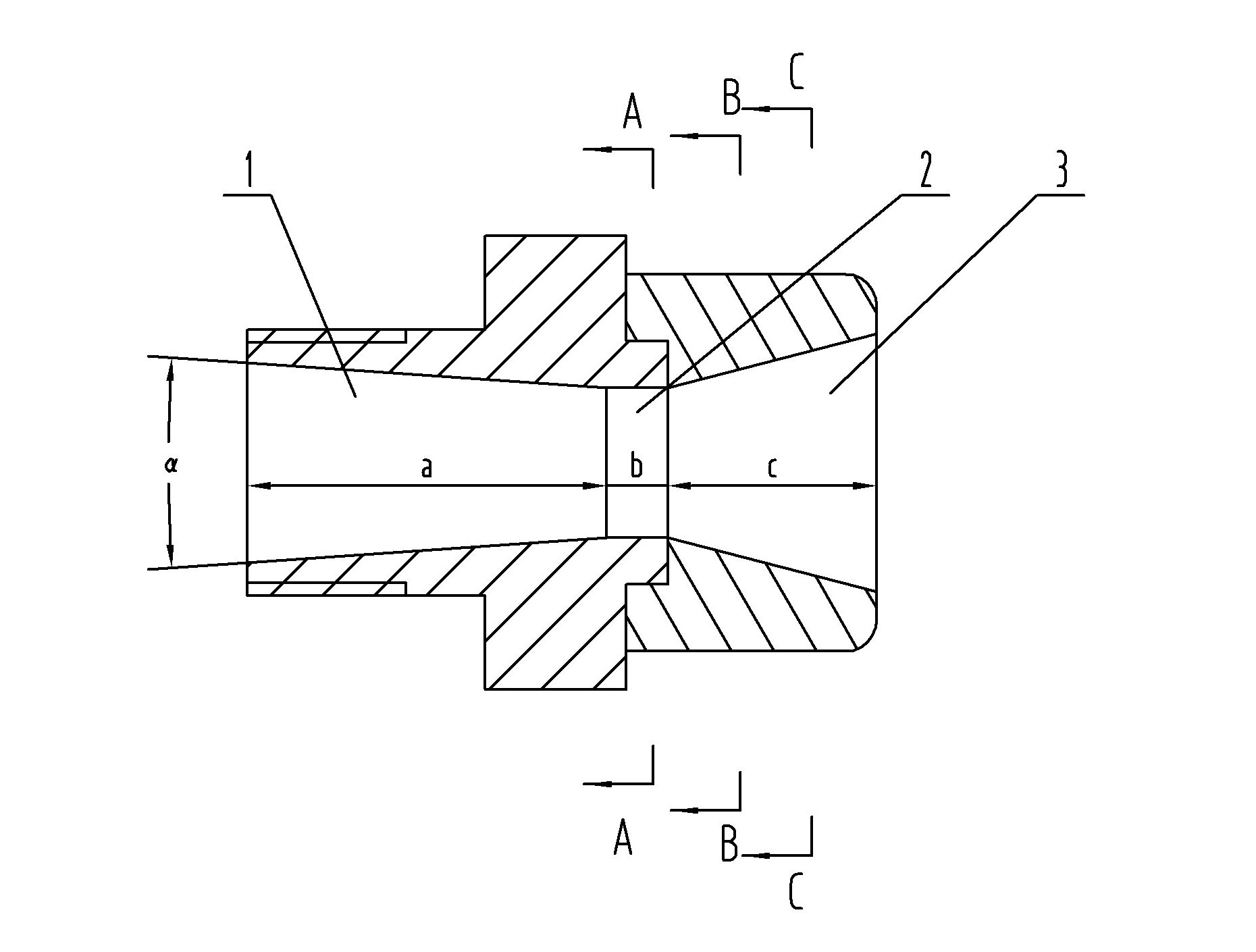
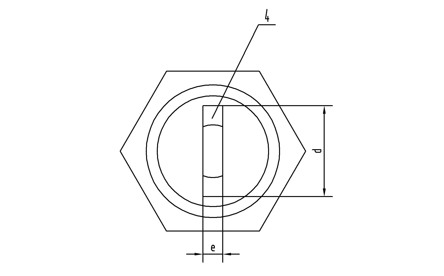
[0034] Embodiment one: see Figure 1 to Figure 5 , in the figure, the flat jet nozzle of the present invention includes shrinkage pipe section 1, throat pipe section 2 and diffuser pipe section 3 from left to right. The shrinkage pipe section 1 is hollow conical, and the range of the cone angle α is 30°≤α≤ 120°, the range of the length a of the shrinkage tube section 1 is 8mm≤a≤30mm, the throat section 2 is hollow cylindrical, the range of the length b of the throat section 2 is 1mm≤b≤4mm, and the inner cavity of the diffusion tube section 3 is The tail of the inner cavity of the throat section 2 gradually transitions to the flat hole 4 on the end face of the nozzle, the range of the length c of the diffuser section 3 is 3mm≤c≤12mm, and the range of the height d of the flat hole 4 is 3mm≤d≤12mm, the flat hole The range of the width e of 4 is 1.5mm≤d≤6mm; the flat hole 4 is an approximately flat rectangular hole; the shrinkage pipe section 1 and the throat pipe section 2 are in...

Embodiment 2

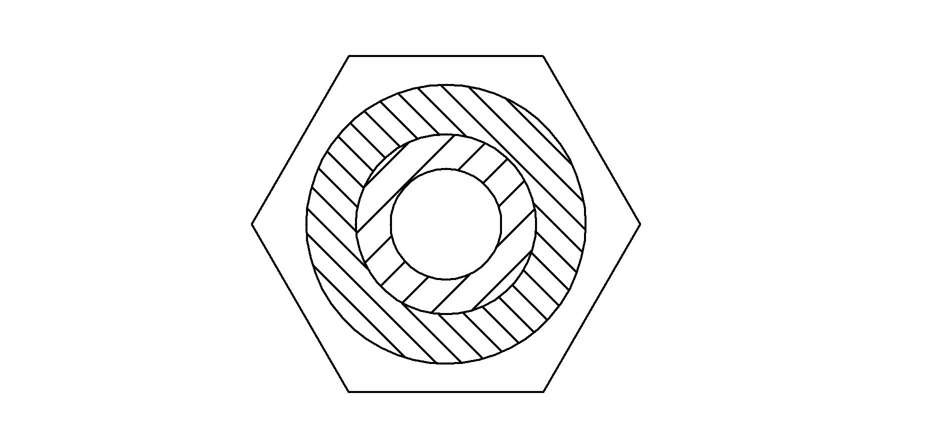
[0035] Embodiment two: see Image 6 , in the figure, the meanings of the same numbered parts in this embodiment and the first embodiment are the same and will not be repeated. The difference is that the flat hole 4 described in this embodiment is an approximately oblong circular hole.

Embodiment 3

[0036] Embodiment three: see Figure 7 , in the figure, the meanings of the same numbered parts in this embodiment and the first embodiment are the same and will not be repeated. The difference is that the flat hole 4 described in this embodiment is an approximately flat oval hole.


PUM


Abstract

The invention belongs to the technical field of building machinery, and particularly relates to a flat jet flow nozzle and a special coating machine which are used for coating various materials on surfaces of the inner wall and the outer wall of a building. The flat jet flow nozzle comprises a shrinkage pipe section, a throat pipe section and a diffuse pipe section from left to right in sequence, the shrinkage pipe section is in a hollow cone shape, the cone angle alpha is in a range being greater than or equal to 30 degrees and less than or equal to 120 degrees, the length of the shrinkage pipe section a is in a range being greater than or equal to 8mm and less than or equal to 30mm, the throat pipe section is in a hollow cylinder shape, the length of the throat pipe section b is in a range being greater than or equal to 1mm and less than or equal to 4mm, an inner cavity of the diffuse pipe section is a flat hole which is formed in a way that the tail of an inner cavity of the throat pipe section gradually transits to the end surface of the tail end of the nozzle, the length of the diffuse pipe section c is in a range being greater than or equal to 3mm and less than or equal to 12mm, the height of the flat hole d is in a range being greater than or equal to 3mm and less than or equal to 12mm, and the width of the flat hole e is in a range being greater than or equal to 1.5mm and less than or equal to 6mm. In the nozzle and the coating machine which are provided by the invention, the coating effect is uniform and smooth, the bonding degree of the materials and a wall body is high, the compactness of the materials is high, the coating efficiency is high, the coating quality is ensured, and further the special coating machine is wide in application range, obvious in economic benefit, and is beneficial to popularization and application.

Description

technical field [0001] The invention belongs to the technical field of construction machinery, and in particular relates to a flat jet nozzle and a special spraying machine for spraying various materials on the inner and outer walls of buildings. Background technique [0002] At present, the traditional methods of manual operation are still used in the construction of the interior and exterior walls of buildings in our country, such as manual plastering, manual putty scraping and other methods, so that the wall surface can achieve a smooth effect. However, its method has high labor intensity and low efficiency, and its quality cannot be guaranteed. Although the existing spraying machine used has greatly reduced the labor intensity of workers and significantly improved the construction efficiency, the effect and quality of spraying need to be further improved. Such as the existing spraying machine, in the construction process, the material is sprayed onto the wall surface th...

Claims


Application Information

Patent Timeline
Patent Type & Authority Applications(China)
IPC IPC(8): E04F21/12B05B1/04
Inventor 董世远
Owner 河南恒睿机械制造有限公司
Why Eureka
Try Eureka