Construction method of circular reinforced concrete chimney cylinder wall and hydraulic sliding mould device

A technology of reinforced concrete and construction method, which is applied in the fields of formwork/formwork/work frame, preparation of building components on site, construction, etc., which can solve the problem of large shaking of the central hanging cage, slow lifting speed of the central hanging cage, and vertical transportation of construction materials. Insecurity and other problems, to achieve the effect of small construction space, few participants in the war, and conducive to disassembly, transportation and reuse

Active Publication Date: 2012-07-04
马鞍山钢铁建设集团有限公司
View PDF9 Cites 35 Cited by
  • Summary
  • Abstract
  • Description
  • Claims
  • Application Information

AI Technical Summary

Problems solved by technology

Its disadvantages are: when constructing a chimney with a high height, the center cage shakes a lot along the flexible slideway during the lifting process, which is unsafe for construction personnel to go up and down and the vertical transportation of some construction materials, and the lifting speed of the center cage slow

Method used


Image

  • Construction method of circular reinforced concrete chimney cylinder wall and hydraulic sliding mould device
  • Construction method of circular reinforced concrete chimney cylinder wall and hydraulic sliding mould device
  • Construction method of circular reinforced concrete chimney cylinder wall and hydraulic sliding mould device

Examples


Embodiment Construction

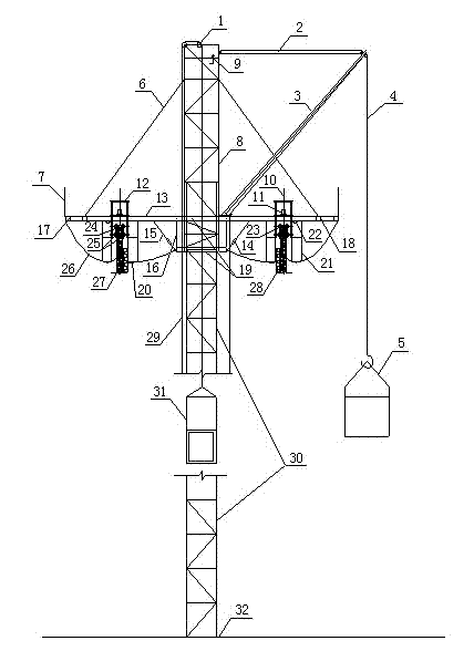
[0022] As shown in the figure, the fixed derrick steel plate embedded parts 32 are pre-embedded in advance on the chimney foundation constructed by conventional inverted moulds, and the fixed derrick 29 is erected. The fixed derrick 29 is made of angle steel sections, connected by high-strength bolts, and the lower end of the fixed derrick is welded and fixed at On the steel plate embedded part 32, the upper end of the fixed derrick extends into the ascending derrick 8 and is higher than the construction operation platform by a certain height; the conventional inverted mold is used to construct the chimney wall 27 of a certain height, and the support rod 10 is pre-embedded in the wrong head by 25% In the chimney tube wall 27 that has been constructed, the supporting rod 10 is generally made of Φ48mm×3.5mm steel pipes, which are connected by welding. The number of supporting rods 10 is determined in advance according to the design of the slipform construction device; the hydraulic...


PUM


Abstract

The invention discloses a construction method of a circular reinforced concrete chimney cylinder wall, and a hydraulic sliding mould device, wherein a hydraulic sliding mould construction method is a rapid construction method of dynamically and continuously molding concrete; loads such as an operation platform and a template are completely supported on a support rod which is stabilized by low-age concrete and has small rigidity; the operation platform and the template are driven to climb along the cylinder wall by a hydraulic jack; and the hydraulic jack climbs on the support rod by an oil path system. The hydraulic sliding mould construction employing the sliding mould as an external cylinder wall and building a lining adopts an ''outside sliding and inside building'' construction process featured by synchronously constructing the external cylinder wall and the lining. The hydraulic sliding mould construction is featured by dynamic continuous construction, having fast construction speed in comparison with mould reverse, symmetrically distributing the hydraulic jack on the circumference of the chimney cylinder wall, forming the template by combining a fixed template with a moveable plate and a contracting and separating template, convenient to assemble and dismount as well as regulate the diameter and the circumference of the combined template structure, capable of gradually decreasing the diameter and the circumference of the combined template structure along with the diameter change of the chimney diameter. The hydraulic sliding mould construction is advantaged in few invested construction operators and convenient management.

Description

Technical field [0001] The invention relates to a construction method of a circular reinforced concrete chimney tube wall and a hydraulic slipform device. Background technique [0002] The construction technology of circular reinforced concrete chimney tube wall slipform has been used in my country since the 1970s, and it has been developed to the present. In the slipform process, there are sliding frame inverted molds, external sliding internal lifting, external sliding internal masonry and self-elevating platform turning Mould and hydraulic sliding mould without derrick, etc. For vertical transportation, electric hoist is used to lift the hanging cage set in the center of the chimney through the follow-up mast or directly use construction hoist, etc. [0003] Vertical transportation without derrick hydraulic sliding form adopts electric hoist to lift the hanging cage located in the center of the chimney through the ascending derrick. Generally, the height of the ascending derrick...

Claims


Application Information

Patent Timeline
Patent Type & Authority Applications(China)
IPC IPC(8): E04G21/00E04G11/22
Inventor 刘识斌
Owner 马鞍山钢铁建设集团有限公司
Why Eureka
Try Eureka