Pneumatic and structural feature considered three-dimensional geometric structure of fan blade of aircraft engine

A technology with structural features and three-dimensional geometry, which is applied in the direction of engine components, machines/engines, blade support elements, etc., can solve the problems of large flow separation loss, excessive stress at the root extension section, and difficulty in blade installation, so as to improve the import conditions , improve efficiency and reduce the effect of Mach number

Inactive Publication Date: 2014-09-10
BEIHANG UNIV
View PDF4 Cites 0 Cited by
  • Summary
  • Abstract
  • Description
  • Claims
  • Application Information

AI Technical Summary

Problems solved by technology

However, studies have shown that the design of equal power distribution cannot minimize the radial mixing of the flow. In terms of aerodynamics, low-energy gas accumulates in the corner area formed by the suction surface of the trailing edge and the hub, and the loss of flow separation is very large. At the same time, it also makes the inner outlet of the fan The high Mach number increases the difficulty and risk of supercharging stage design; in terms of structure, the small angle between the suction surface and the hub is also not conducive to the structural shape of the root section, which makes it difficult to install the blade on the wheel , it is possible to generate excessive stress in the root section

Method used


Image

  • Pneumatic and structural feature considered three-dimensional geometric structure of fan blade of aircraft engine
  • Pneumatic and structural feature considered three-dimensional geometric structure of fan blade of aircraft engine
  • Pneumatic and structural feature considered three-dimensional geometric structure of fan blade of aircraft engine

Examples


Embodiment Construction

[0020] The technical solution of the present invention will be further described below in conjunction with the drawings and embodiments.

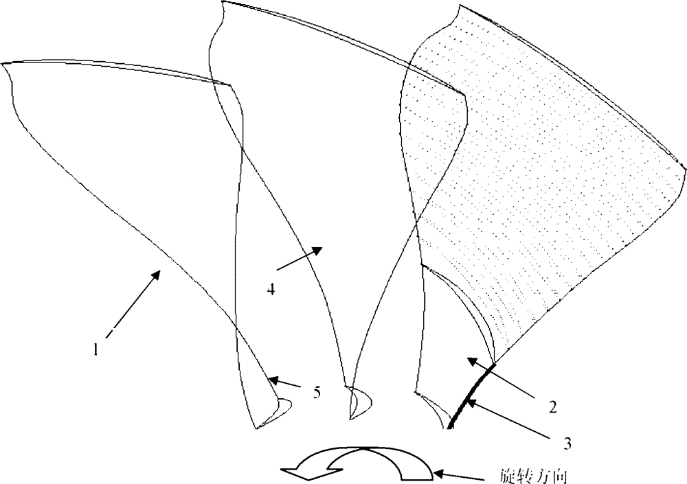
[0021] A three-dimensional geometric structure of the connotation blade of a large fan of a civil aviation engine that takes into account both aerodynamic and structural characteristics, wherein the connotation blade refers to the 0-20% blade height part of the large fan blade, which is characterized by:

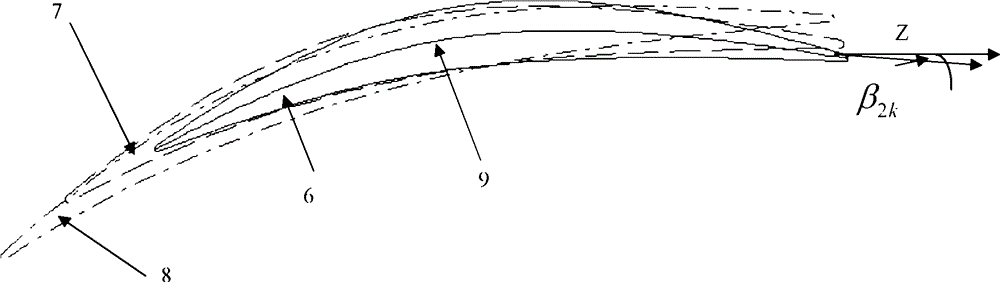
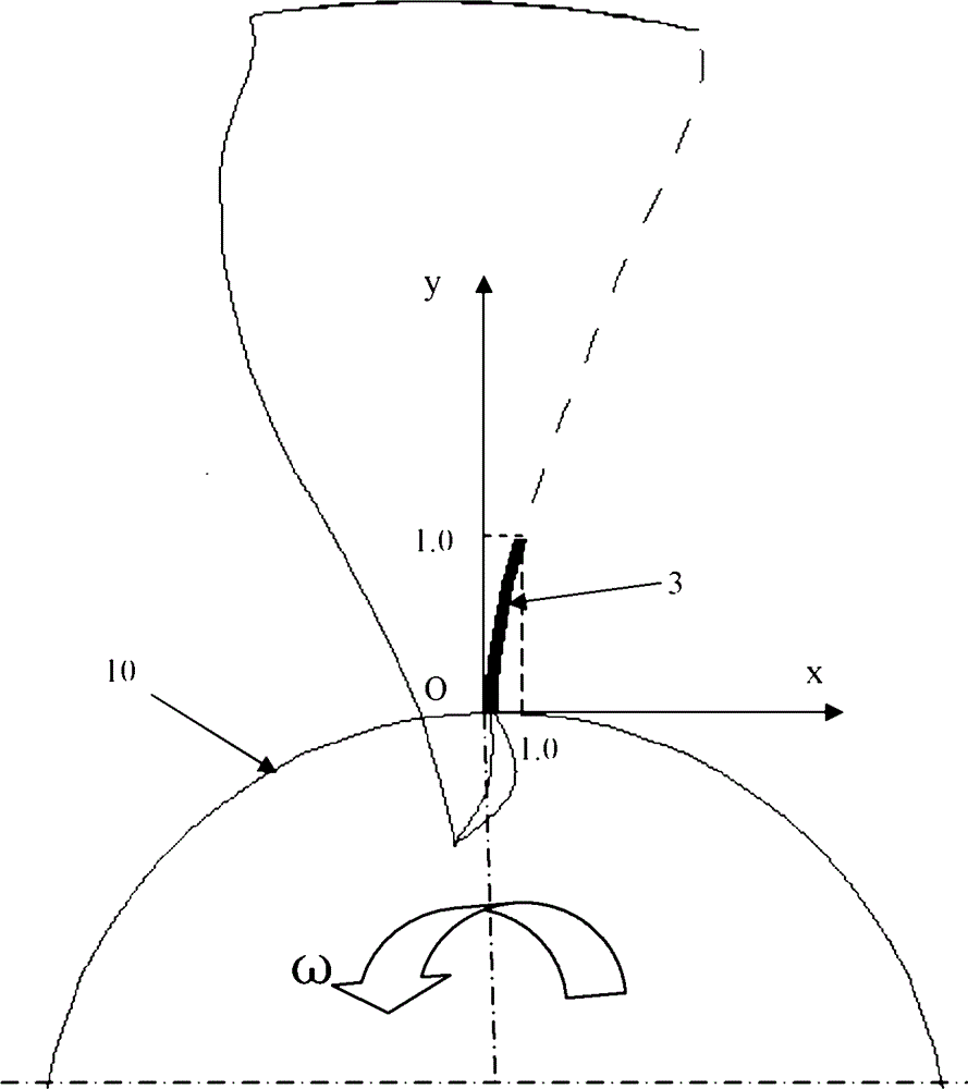
[0022] 1. The exit metal angle β of the 2 elementary leaf shape of the inner blade 2k (Such as figure 2 As shown, the tangent and axial direction of the middle arc at the trailing edge point The included angle, clockwise is positive) The distribution along the spread height can be described by a cubic polynomial

[0023] y=79.804x 3 +70.411x 2 +33.222x-8.62

[0024] Among them, x is the percentage of the relative extension, y is the exit metal angle of the corresponding leaf height element blade profile, in degrees (°), and the tolerance range o...


PUM


Abstract

The invention discloses a pneumatic and structural feature considered three-dimensional geometric structure of a large fan connotative blade of a civil aircraft engine. The rear section of a blade profile at the root part of the large fan which is designed traditionally has a larger bent corner, a smaller acute angle is formed by a trailing edge suction surface and a hub, low-energy gas is accumulated in the acute-angle area, the flow loss is great, and the smaller acute angle between the suction surface and the hub is not beneficial to the structure modeling of the root stretching section of the blade. According to the invention, the change of an outlet metal corner of an element blade profile of the large fan connotative blade (which is the part within 20% of a blade height of the large fan blade) along the blade height is mainly optimized and a distribution curve of the outlet metal corner of a connotative blade and a projection curve of a trailing edge line in a plane vertical to the axial direction are fit. Through the verification of three-dimensional CFD (Computational Fluid Dynamics), the pneumatic and structural feature considered three-dimensional geometric structure disclosed by the invention has the advantages that the flow separation in the acute-angle area formed by the trailing edge suction surface of the fan and the hub can be effectively reduced, the fan connotative efficiency can be increased, a good entrance condition is provided for a pressure boosting grade, and the blade at the root part and the hub are relatively almost vertical, so that convenience is provided for the installation of the blade on a wheel disc.

Description

Technical field [0001] The invention relates to a three-dimensional geometric structure of connotative blades of a large fan of a civil aviation engine that takes into account both aerodynamic and structural characteristics, and belongs to the technical field of impeller mechanical axial compressor impellers. Background technique [0002] Due to the relatively small hub in the large fan of civil aviation engines, the flow parameters change drastically along the radial direction. The traditional design idea is to adopt the law of distribution of high power along the leaf, which is believed to minimize the radial mixing of the flow and reduce the flow loss. Due to the large difference in the tangent speed of the root tip of the large fan, in order to ensure the equal power from the root to the tip of the rim, the basic element blade shape of the internal blade of the fan needs to be twisted greatly, so the traditional fan internal blade trailing edge suction surface and the hub for...

Claims


Application Information

Patent Timeline
Patent Type & Authority Patents(China)
IPC IPC(8): F01D5/14
Inventor 桂幸民孙晓峰金东海朱芳
Owner BEIHANG UNIV
Why Eureka
Try Eureka