Uniform-load thrust sliding bearing group for downhole power drilling tools

A technology for thrust sliding bearings and power drilling tools, which is applied in the direction of sliding contact bearings, rotating bearings, bearings, etc., and can solve the problem of bearing group load sharing design and lack of lubrication performance, which is difficult to adapt to ultra-deep well high temperature working environment, single-width bearings Unstable life of the bearing group and other problems, to achieve the effect of compact structure, good wear resistance and short length

Inactive Publication Date: 2012-07-04
SOUTHWEST PETROLEUM UNIV
View PDF5 Cites 5 Cited by
  • Summary
  • Abstract
  • Description
  • Claims
  • Application Information

AI Technical Summary

Problems solved by technology

The number of components in the ball bearing group is large, and the installation and adjustment accuracy is high. The bearing group is often loaded unevenly due to unreasonable bearing clearance, and excessive wear and impact crushing are prone to occur under high-speed and heavy loads. Group lifetime is unstable
When working in high temperature, the diamond thrust plate is prone to overheating and wear, and it is difficult to adapt to the high temperature working environment of ultra-deep wells
The load-sharing design and lubrication performance of the above-mentioned types of bearing groups are lacking, and the load-sharing performance of the bearing group has decisive significance for the life of the downhole power drilling tool bearing group

Method used


Image

  • Uniform-load thrust sliding bearing group for downhole power drilling tools
  • Uniform-load thrust sliding bearing group for downhole power drilling tools
  • Uniform-load thrust sliding bearing group for downhole power drilling tools

Examples


Embodiment Construction

[0016] Embodiments of the present invention will be specifically described below in conjunction with the accompanying drawings.

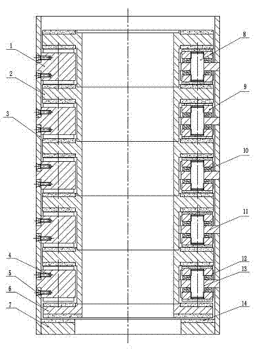
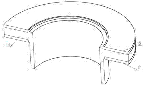
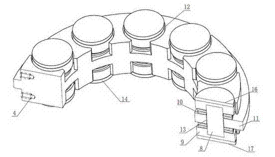
[0017] Such as figure 1 , figure 2 , image 3 , Figure 4 As shown, a load sharing thrust sliding bearing group of a downhole power drilling tool according to the present invention is mainly composed of a static ring 1, a moving ring 2, an outer sleeve 3, an overload protection moving ring 6 and an overload protection static ring 7. The static ring is composed of a connecting stud 8, a thrust tile 9, a butterfly spring 10, and a static ring base 11; 10 to 16 counterbores 12 are evenly distributed on the circumference of the front and back sides of the static ring base 11, and the counterbores There is a through hole 13 in the center of 12; the connecting stud 8 passes through the through hole 13 and is threadedly connected with the thrust tile 9, and the butterfly spring 10 is fixed between the thrust tile 9 and the static ring base 11, and the ...


PUM


Abstract

The invention relates to a uniform-load thrust sliding bearing group for downhole power drilling tools, belonging to the technical field of downhole equipment for oil drilling. The uniform-load thrust sliding bearing group is mainly composed of a static ring, a moving ring, an outer sleeve, an overload protection moving ring and an overload protection static ring; wherein the static ring is composed of a connection stud, a thrust pad, a disk spring and a static ring base; 10-16 counter bores are uniformly distributed in the circumferential directions of the positive and negative surfaces of the static ring base; through holes are arranged at the centers of the counter bores; the connection stud passes through the through holes to be in threaded connection with the thrust pad so as to fix the disk spring between the thrust pad and the static ring base; the disk spring is arranged in a shutting form; 3-8 threaded holes are distributed on the static ring base in the radial direction; the static ring base and the outer sleeve are fixed together by a bolt; and the moving ring and the static ring are connected in series to form the bearing group. According to the uniform-load thrust sliding bearing group, drilling fluid dynamic pressure lubrication can be formed, so that the abrasion of friction surfaces is decreased; the friction surface is made of high-temperature ceramic abrasion resistant materials and has the characteristics of abrasion resistance and corrosion resistance; and the bearing group has a compact structure, so that the mounting, the overhauling and the change of the bearing group are simplified.

Description

technical field [0001] The invention relates to an equal-load thrust sliding bearing group of a downhole power drilling tool, which belongs to the technical field of downhole equipment for oil drilling. Background technique [0002] The rotary drilling method of downhole motors has been widely used. Downhole motors have the advantages of high mechanical penetration rate, precise orientation and small wear of drilling strings in drilling ultra-deep wells, directional wells, cluster wells, and hard formations. , and can be used in conjunction with the measurement-while-drilling system and the PDC bit, which is an important basis for the automation of downhole drilling tool assemblies. [0003] The downhole power drilling tool bearing group is the decisive factor of the life of the downhole power drilling tool. The bearing group bears two-way heavy load in the drilling fluid with abrasive properties, the movement speed is high, the working environment is harsh, and the life of...

Claims


Application Information

Patent Timeline
Patent Type & Authority Applications(China)
IPC IPC(8): F16C17/26F16C33/04
Inventor 苟如意张晓东张也龙平
Owner SOUTHWEST PETROLEUM UNIV
Why Eureka
Try Eureka